11
19
.
STARTER SYSTEM
STARTER SOLENOID
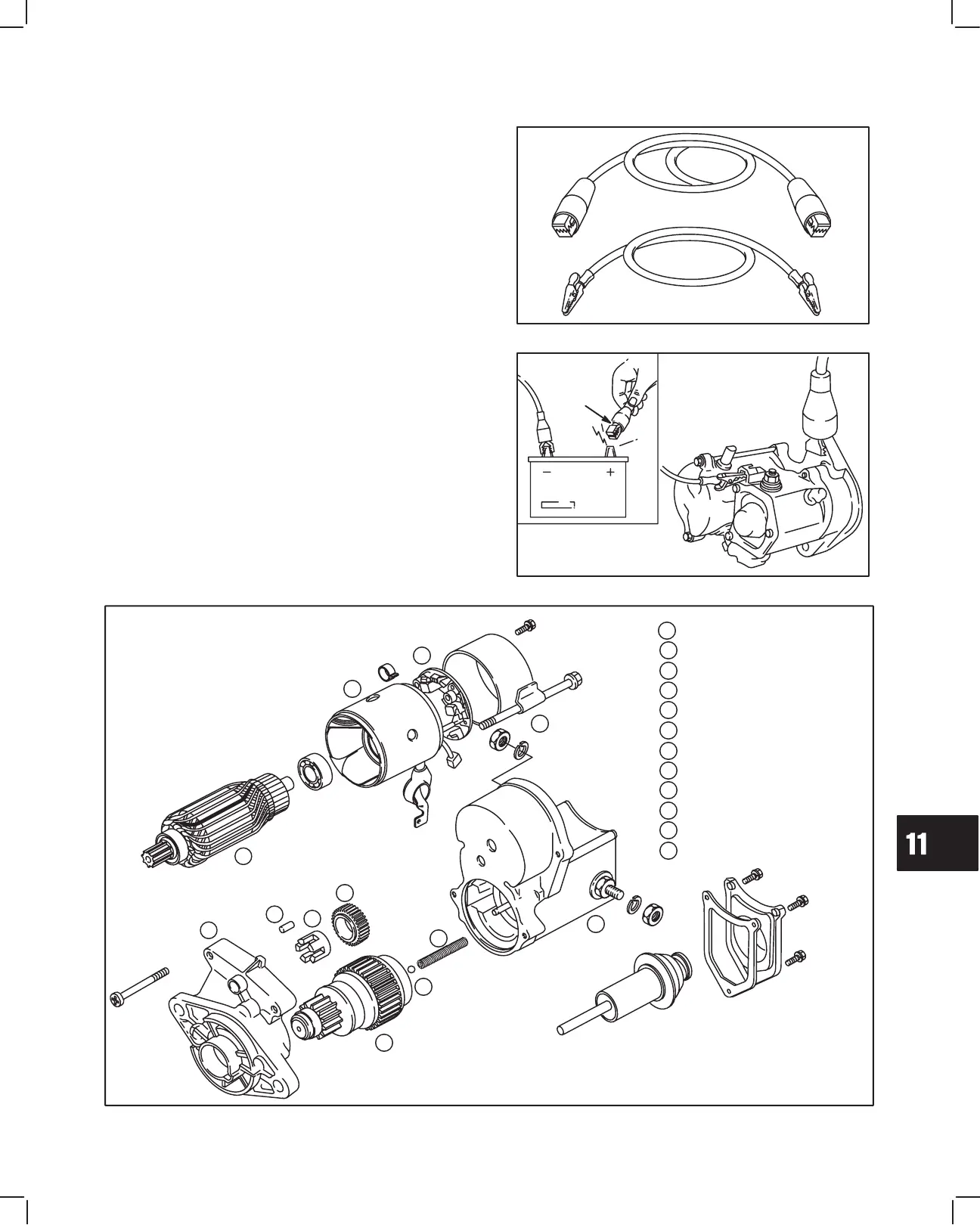
Test Equipment
The starter solenoid test is performed with the starter
removed from the engine.
The following equipment is recommended to test the
solenoid.
1. One battery cable with alligator clips. Fig. 50.
2. A jumper wire.
3. A fully charged 12 volt battery.
Fig. 50 – Test Equipment
JUMPER
WIRE
BATTERY
CABLE
Testing Starter Solenoid
1. Attach one end of battery cable to negative battery
terminal and other end of cable to a good ground
such as drive housing. Fig. 51.
2. Attach jumper wire to tab terminal on solenoid.
3. Activate solenoid by contacting positive battery
terminal with other end of jumper wire.
a. Pinion must move outward quickly (engage).
4. Remove jumper wire from positive battery terminal.
a. Pinion must return quickly (disengage).
If pinion does not move, replace the solenoid.
Fig. 51 – Testing Solenoid
JUMPER
WIRE
DRIVE HOUSING
PINION AND DRIVE CLUTCH
DRIVE GEAR
RETAINER
ROLLER BEARINGS (5)
BALL
RETURN SPRING
SOLENOID
ARMATURE
STARTER HOUSING
BRUSH RETAINER
END CAP
3
4
5
6
7
2
8
12
11
10
9
1
2
3
4
5
6
7
8
9
10
11
12
1
EXPLODED VIEW OF STARTER – TYPICAL
 Loading...