3 - 8
Main unit
Main parts
9 Upper shaft assembly attachment
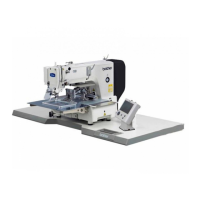
1. Pass timing belt 420-5GT-6 (timing belt) 2 and timing belt 372-2GT-6
(motor belt) 3 to the upper shaft assembly 1.
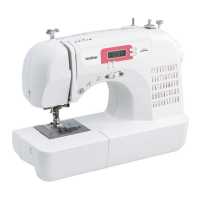
2. Attach the needle bar crank 5 to the thread take-up lever crank 4.
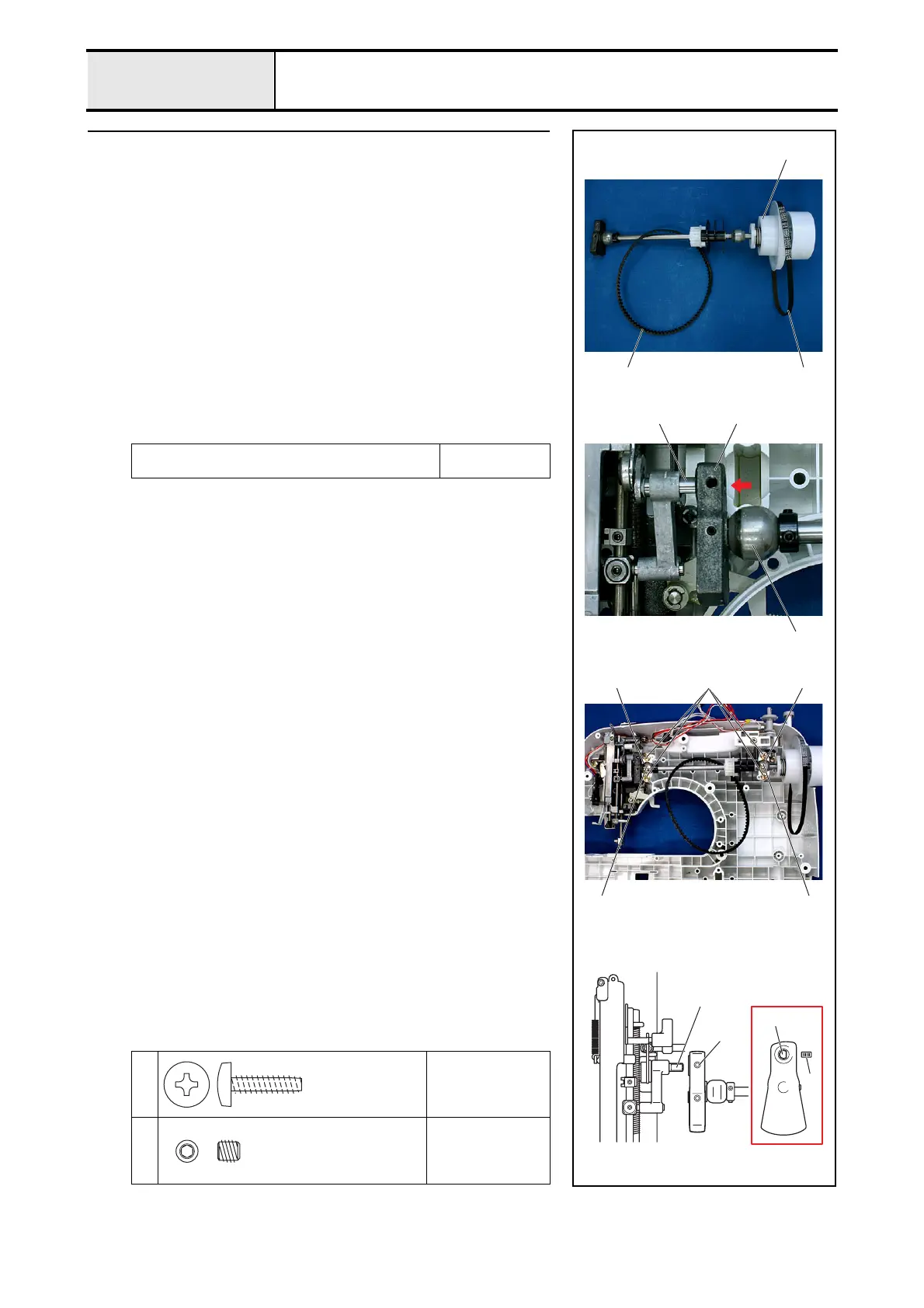
3. Set the upper shaft bushing 6 to the arm bed cover attachment position.
4. Attach the 2 upper shaft bearing pressers 78 with the 4 screws 1.
*Key point
• Check that the bobbin base assembly is on the left side.
• Attach the left upper shaft bearing presser 7 so that the
projecting part of 7 is positioned at the upper right. And attach
the right upper shaft bearing presser 8 so that the projecting
part of 8 is positioned at the lower shaft.
5. Apply 1 or 2 drops of OILER to the matching section of the upper shaft
and the upper shaft bushing.
6. Align the D-cut face of the needle bar crank with the screw hole on the
thread take-up lever crank, and tighten the screw 2.
Apply OILER to the matching section of the upper shaft
and the upper shaft bushing.
1 - 2 drops
XZ0206***
1
Torque
1.18 – 1.57 N
·m
2
Torque
1.18 – 1.57 N
·m
66
7 1 8
1
23
54
6
2
D cut face
D cut face
2
Giza Tite
5X16
Color; Gold
Set Screw, Socket (FT)
M5X5
Color; Black
 Loading...