3 - 13
Main parts
Main unit
Assembly
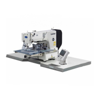
17 Main PCB assembly attachment
1. Insert the bobbin winder switch of the main PCB 2 into the slot on the
bobbin winder stopper plate 1, and then insert the boss on the arm bed
cover into the screw hole on the shutter cover 3.
2. Main PCB assembly 4 with the 2 screw 1.
*Key point
• Refer to "5 - 1 Special Instructions of Wiring" for wiring details.
1
Torque
0.78 – 1.18 N
·m
1
4
1
3
2
Taptite, Bind B
M4X10
Color; Gold
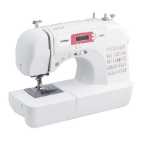
17-1 Main PCB assembly
1. Attach the main PCB plate spring 2 and the main PCB 3 to the shutter
cover 1 with the screw 1.
1
Torque
0.39 – 0.78 N
·m
1 3
12
Taptite, Bind B
M3X8
Color; Gold
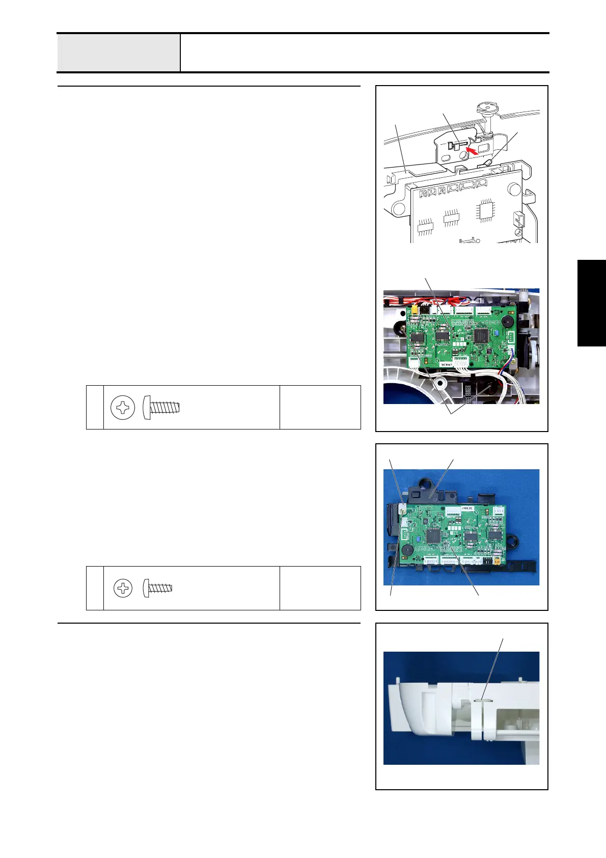
18 Upper cover thread guide attachment
1. Attach the upper cover thread guide 1.
1
 Loading...