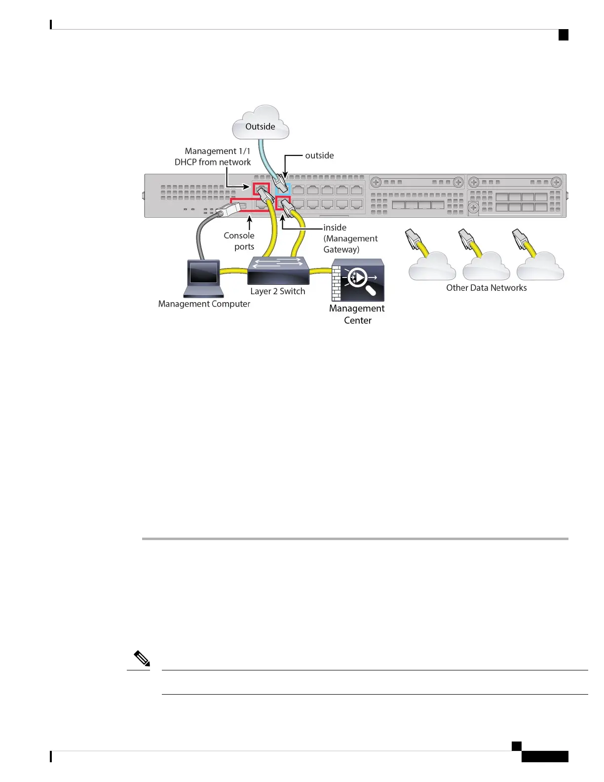
Figure 4: Cabling an Edge Deployment
For version 6.5 and earlier, the Management 1/1 default IP address is 192.168.45.45.
Note
a) Cable the following to a Layer 2 Ethernet switch:
• Inside interface (for example, Ethernet 1/2)
• Management 1/1 interface
• Management Center
• Management computer
b) Connect the management computer to the console port. You need to use the console port to access the
CLI for initial setup if you do not use SSH to the Management interface or use the device manager for
initial setup.
c) Connect the outside interface (for example, Ethernet 1/1) to your outside router.
d) Connect other networks to the remaining interfaces.
Power on the Device
The power switch is located to the left of power supply module 1 on the rear of the chassis. It is a toggle
switch that controls power to the system. If the power switch is in standby position, only the 3.3-V standby
power is enabled from the power supply module and the 12-V main power is OFF. When the switch is in the
ON position, the 12-V main power is turned on and the system boots.
The first time you boot up the threat defense, initialization can take approximately 15 to 30 minutes.
Note
Cisco Firepower 2100 Getting Started Guide
11
Threat Defense Deployment with the Management Center
Power on the Device
 Loading...