Low-touch provisioning supports connecting to CDO on Ethernet 1/1 (outside).
Procedure
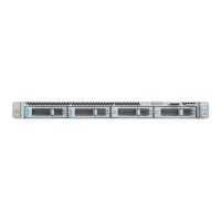
Step 1 Install the chassis. See the hardware installation guide.
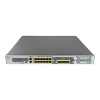
Step 2 Connect the network cable from the Ethernet 1/1 interface to your wide area network (WAN) modem. Your
WAN modem is your branch's connection to the internet and will be your firewall's route to the internet as
well.
Step 3 Connect the inside interface (for example, Ethernet 1/2) to your inside switch or router.
You can choose any interface for inside.
Step 4 Connect other networks to the remaining interfaces.
Step 5 (Optional) Connect the management computer to the console port.
At the branch office, the console connection is not required for everyday use; however, it may be required
for troubleshooting purposes.
Power On the Firewall
The power switch is located to the left of power supply module 1 on the rear of the chassis. It is a toggle
switch that controls power to the system. If the power switch is in standby position, only the 3.3-V standby
power is enabled from the power supply module and the 12-V main power is OFF. When the switch is in the
ON position, the 12-V main power is turned on and the system boots.
The first time you boot up the threat defense, initialization can take approximately 15 to 30 minutes.
Note
Before you begin
It's important that you provide reliable power for your device (for example, using an uninterruptable power
supply (UPS)). Loss of power without first shutting down can cause serious file system damage. There are
many processes running in the background all the time, and losing power does not allow the graceful shutdown
of your system.
Procedure
Step 1 Attach the power cord to the device and connect it to an electrical outlet.
Step 2 Press the power switch on the back of the device.
Step 3 Check the PWR LED on the front of the device; if it is solid green, the device is powered on.
Cisco Firepower 2100 Getting Started Guide
135
Threat Defense Deployment with CDO
Power On the Firewall
 Loading...