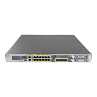
Step 4 Connect the outside network to the Ethernet1/1 interface (labeled WAN).
For Smart Software Licensing, the ASA needs internet access so that it can access the License Authority.
Step 5 Connect the inside network to Ethernet1/2.
Step 6 Connect other networks to the remaining interfaces.
Power on the Firewall
The power switch is located to the left of power supply module 1 on the rear of the chassis. It is a toggle
switch that controls power to the system. If the power switch is in standby position, only the 3.3-V standby
power is enabled from the power supply module and the 12-V main power is OFF. When the switch is in the
ON position, the 12-V main power is turned on and the system boots.
Procedure
Step 1 Attach the power cord to the device and connect it to an electrical outlet.
Step 2 Press the power switch on the back of the device.
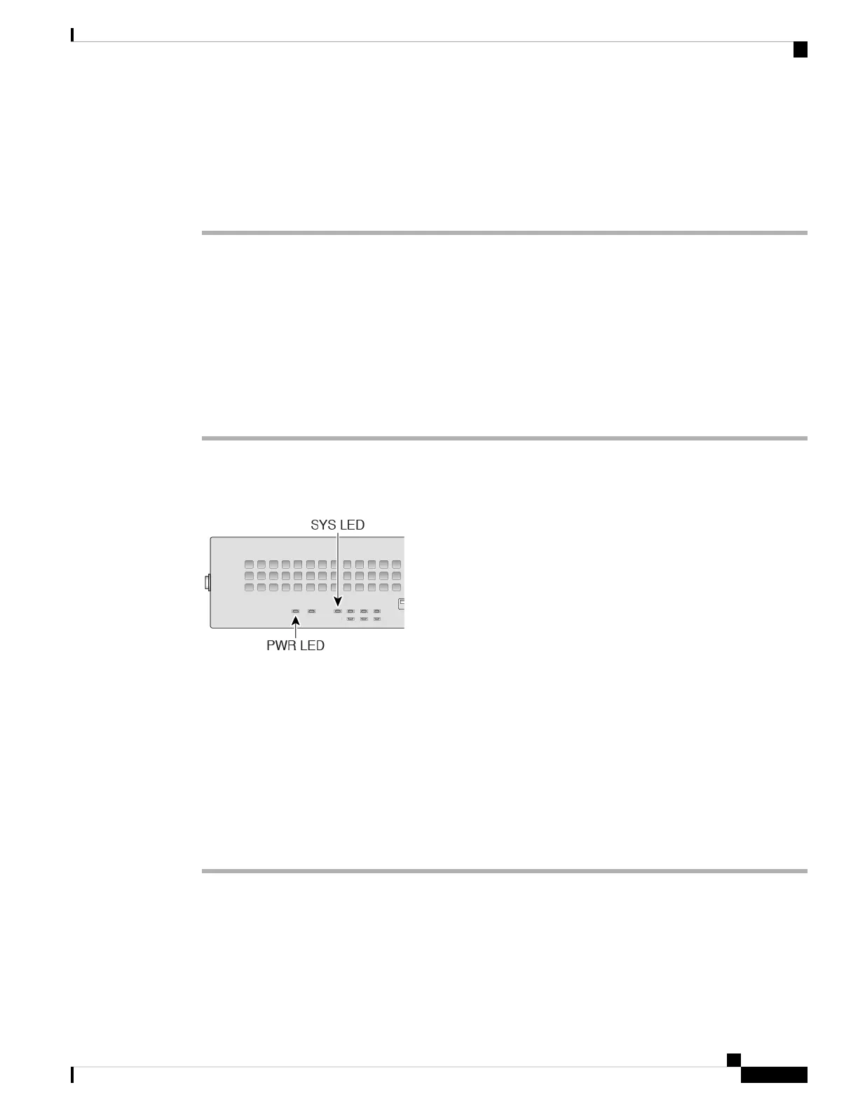
Step 3 Check the PWR LED on the front of the device; if it is solid green, the device is powered on.
Step 4 Check the SYS LED on the front of the device; after it is solid green, the system has passed power-on
diagnostics.
Before you move the power switch to the OFF position, use the shutdown commands so that the
system can perform a graceful shutdown. This may take several minutes to complete. After the
graceful shutdown is complete, the console displays It is safe to power off now. The front
panel blue locator beacon LED lights up indicating the system is ready to be powered off. You
can now move the switch to the OFF position. The front panel PWR LED flashes momentarily
and turns off. Do not remove the power until the PWR LED is completely off.
See the FXOS Configuration Guide for more information on using the shutdown commands.
Note
Enable Platform Mode
The Firepower 2100 runs in Appliance mode by default. This procedure tells you how to change the mode to
Platform mode, and optionally how to change it back to Appliance mode.
Cisco Firepower 2100 Getting Started Guide
205
ASA Deployment with ASDM
Power on the Firewall
 Loading...