ED34-862 Installation
FXUQ-MA 401
12
10.2 Connecting Units
Before Installation
Service Space.
• See the included installation manuals on the VRV outdoor unit and the ceiling suspended cassette type
indoor unit for details.
• For the indoor unit connected to the BEV unit, cooling/heating cannot be switched over with the remote con-
troller.
• When the cooling/heating free system is connected to the BS unit, a cooling/heating selection right is
allowed.
• When the ceiling suspended cassette type indoor unit and BEV unit are used for all indoor units, a separate
“Cool/Heat SELECTOR” is needed to enable the cooling/heating switchover.
• When moving the unit while removing it from the carton box, be sure to lift it by holding on to the
two lifting lugs without exerting any pressure on other parts, especially, the refrigerant piping.
• Be sure to check the type of R-410A refrigerant to be used before installing the unit. (Using an incorrect
refrigerant will prevent normal operation of the unit.)
• BEV unit is an electronic expansion valve unit for allowing the indoor unit to be connected to the system for
the VRV system.
• BEV unit may only be connected to the models shown in the table below. Do not attempt connection with
other models.
Indoor unit
Ceiling Suspended Cassette Type
*
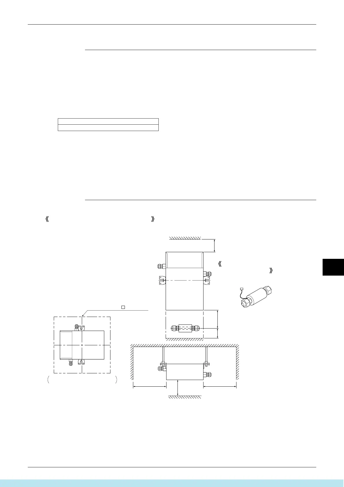
or more
100
Maintenance hole 450 or more
Be sure to create a maintenance hole
the size shown in the figure above.
200 or more
200 or more
400 or more
**
(Service space)
100-250
When hanging the unit from the ceiling
**
If the Maintenance hole cannot be installed
directly below, make sure there is at least
400mm of space.
* Make sure there is enough space to tighten the flare nuts.
Fig. 1
(length: mm)
Install so that the control box lid is facing down.
Take the gas piping thermistor out
from above.
Horizontal position
Direction of the gas piping
connection piping
Все каталоги и инструкции здесь: http://splitoff.ru/tehn-doc.html

 Loading...