3 Electrical Diagrams
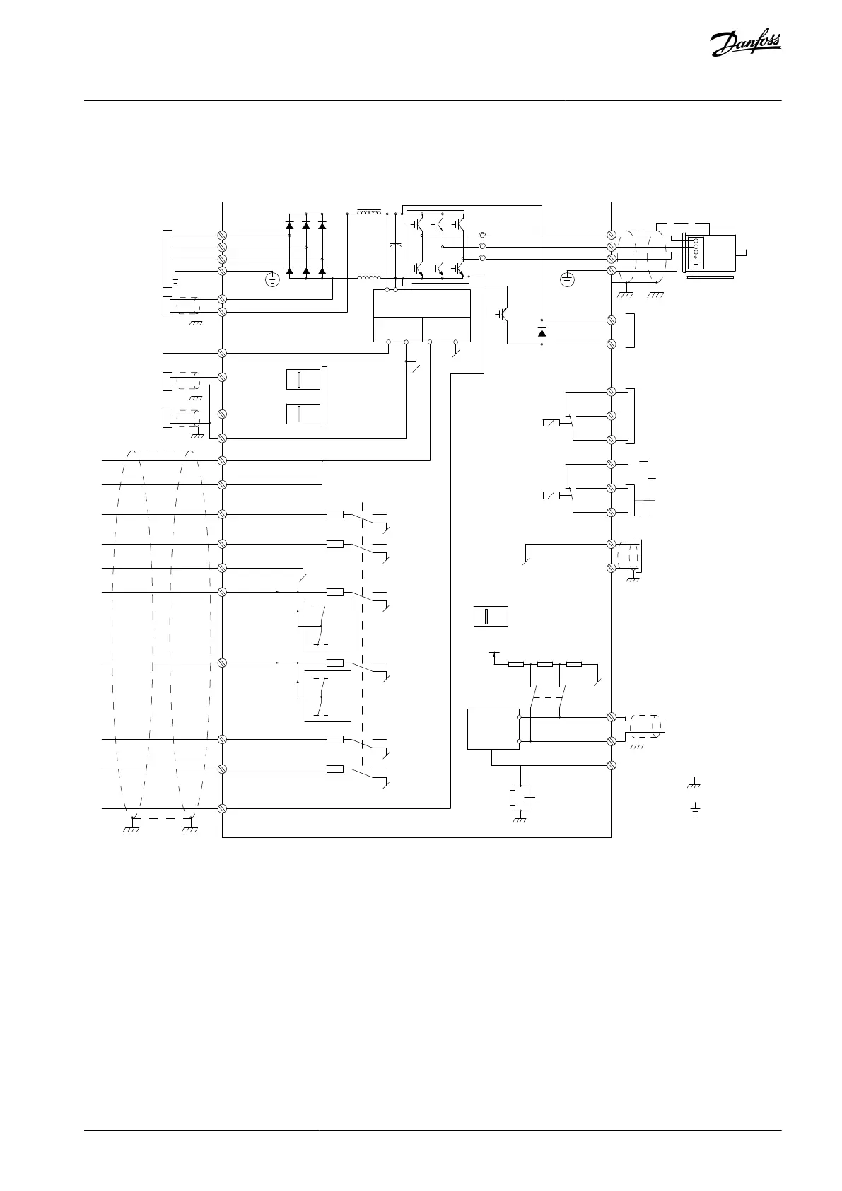
3.1 Wiring Schematic
Power Supply
Motor
Analog Output
Interface
relay 1
relay 2
ON=Terminated
OFF=Open
Brake
resistor
e30bc931.13
88 (-)
89 (+)
50 (+10 V OUT)
53 (A IN)
54 (A IN)
55 (COM A IN)
12 (+24 V OUT)
13 (+24 V OUT)
37 (D IN)
18 (D IN)
20
+ - + -
(U) 96
(V) 97
(W) 98
(PE) 99
(COM A OUT) 39
(A OUT) 42
(P RS485) 68
(N RS485) 69
(COM RS485) 61
0V
5V
S801
0/4-20 mA
RS485
RS485
03
+10 V DC
0/-10 V DC -
+10 V DC
+10 V DC
0/4-20 mA
0/-10 V DC -
240 V AC, 2 A
24 V DC
02
01
05
04
06
240 V AC, 2 A
24 V (PNP)
0 V (NPN)
0 V (NPN)
24 V (PNP)
24 V
0 V
(D IN/OUT)
0 V (NPN)
24 V (PNP)
(D IN/OUT)
0 V
24 V
24 V (PNP)
0 V (NPN)
0 V (NPN)
24 V (PNP)
1 2
ON
S201
ON
21
S202
ON=0/4-20 mA
OFF=0/-10 V DC -
+10 V DC
95
400 V AC, 2 A
Par. 5-00
21
ON
S801
(R+) 82
(R-) 81
: Chassis
: Earth
1)
2)
1)
Illustration 1: Wiring Schematic
A=Analog, D=Digital
1) Do not connect cable shield.
Terminal 37 is used for Safe Torque Off (STO). For STO installation instructions, refer to the VLT® Frequency Converters - Safe Torque
Off Operating Guide.
Long control cables and analog signals may in rare cases, depending on installation, result in 50/60 Hz ground loops due to noise
from mains supply cables. If 50/60 Hz ground loops occur, consider breaking the shield or insert a 100 nF capacitor between shield
and enclosure.
To avoid ground currents from both groups to affect other groups, connect the digital and analog inputs and outputs separately to
the common inputs (terminals 20, 55, and 39) of the drive. For example, switching on the digital input may disturb the analog input
signal.
AU275636650261en-000101 / 130R0334 | 15Danfoss A/S © 2022.12
Electrical Diagrams
VLT AutomationDrive FC 301/302
Programming Guide
 Loading...


