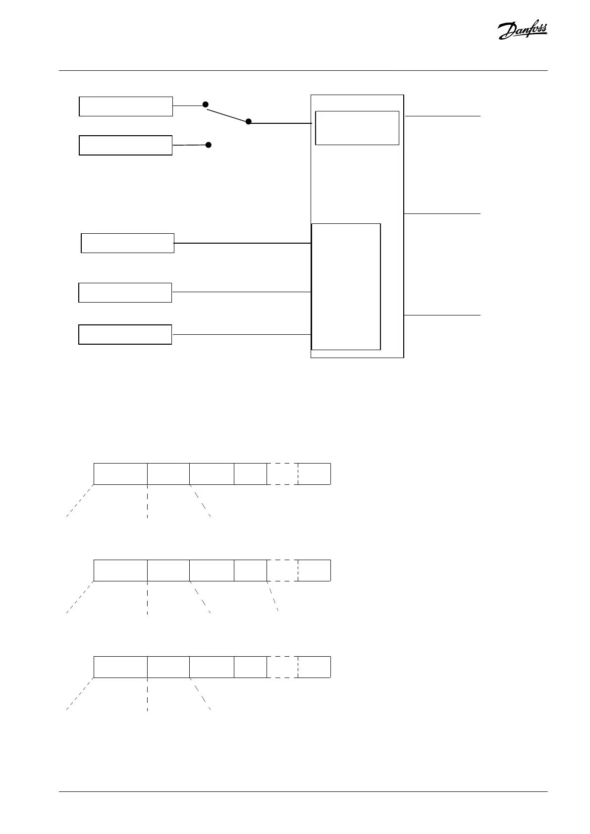
Position ref.
Acceleration/Deceleration
Speed ref.
Fieldbus Sync. REF
Master position
Par. 3-16 Reference Resource 2
Par. 3-26 Position Offset
Par. 3-02 Offset Speed
Ramp Settings:
Parameter groups 3-4* - 3-7*
e30be775.11
Profile generator
Commanded
position
Speed
Acceleration
Offset handling
Synchronization:
Par. 3-22 - 3-25,
7-97,7-99
Illustration 101: Synchronization References
In each control cycle (1 ms), the profile generator calculates position, speed, and acceleration required to do the specified move-
ment. The outputs from the profile generator are used as inputs for the position and speed controller.
6.2.4 Fieldbus References
Fieldbus references for speed and position are set via the process data (PCD) configuration as shown in the example:
Control word
Target Position
16 bit
e30bg868.11
PCD 0 PCD 1
PCD 2 PCD 3 PCD X
Illustration 102: Positioning: Default settings (PCD 1 = Fieldbus REF 1)
Control word
Speed Reference
+/- 4000Hex
Target Position
32 bit
e30bg869.11
PCD 0 PCD 1
PCD 2 PCD 3 PCD X
Illustration 103: Positioning: PCD write configuration PCD 1 = Fieldbus REF 1, PCD 2 and 3 = Fieldbus Pos REF
Control word
Master position
e30bg870.11
PCD 0 PCD 1
PCD 2 PCD 3 PCD X
Illustration 104: Synchronizing: PCD write configuration PCD 1 = Fieldbus Sync REF
AU275636650261en-000101 / 130R0334 | 685Danfoss A/S © 2022.12
Integrated Motion Controller
VLT AutomationDrive FC 301/302
Programming Guide
 Loading...


