•
•
6.3 Control
6.3.1 Control Loops
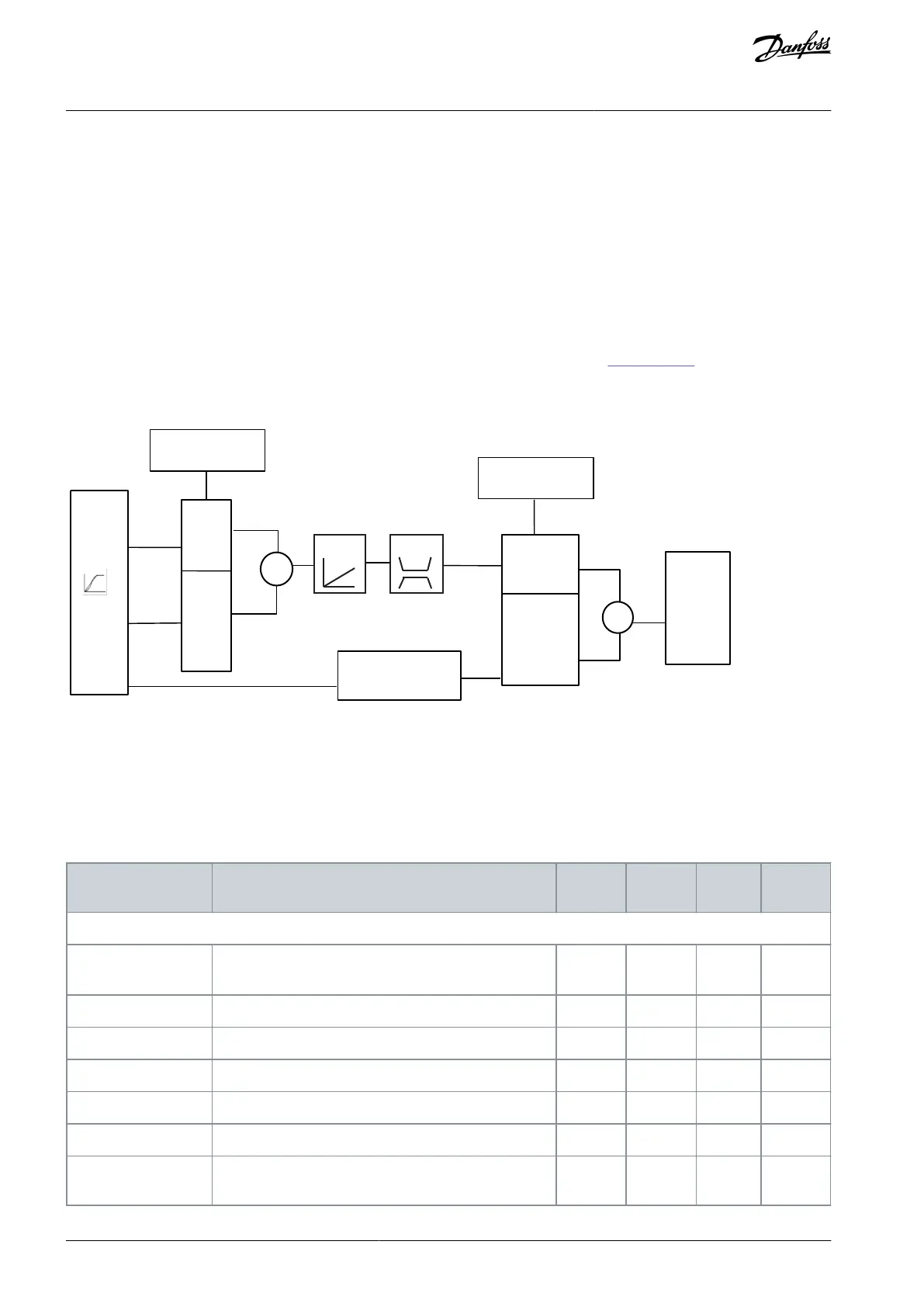
In positioning and synchronization mode, 2 extra control loops control the motor in addition to the motor controller running flux
control principle, sensorless, or with motor feedback. The position PI controller is the outer loop providing the setpoint for the
speed PID, which provides the reference for the motor controller. For a closed loop, feedback source can be selected individually for
each of 3 controllers.
For sensorless control principle, select [0] Motor feedb. P1-02 in the following parameters:
Speed PID: Parameter 7-00 Speed PID Feedback Source.
Position PI: Parameter 7-90 Position PI Feedback Source.
With this set-up, both controllers use the motor angle calculated by the motor controller. See
Illustration 105 for control structure
and parameters affecting the control behavior.
7-9*
Position
PI Ctrl.
Par. 7-98
Position
PI
Feed
Par.7-90 Position PI
Feedback Source
Par. 7-00 Speed PID
Feedback Source
7-0*
Speed PID
Par. 7-08
Speed PID
Accel. Feed forward
factor
Flux motor
control
Ramp
Torque
Acceleration
Par.1-69 System Inertia
e30be776.10
Profile
Generator
Illustration 105: Positioning and Synchronization Mode
6.3.2 Control and Status Signals
IMC control and status signals are available I/O bits and fieldbus bits.
Table 1431: Control and Status Signals
Activates the master offset when parameter 17-93 Master
Offset Selection is set to options [0]–[5].
Starts selected homing function.
Starts the virtual master.
Selects touch probe positioning mode.
Selects between absolute and relative positioning.
Selects positioning in synchronizing mode.
AU275636650261en-000101 / 130R0334686 | Danfoss A/S © 2022.12
Integrated Motion Controller
VLT AutomationDrive FC 301/302
Programming Guide
 Loading...


