TYPE, OPT:
OPT TYPE
7 6 5 4 BIT 3 ~ 0 BIT
- UNIT 22AUTO INS 1: SPEED, Speed setting control
CMD OVLP 2INS
2: SINGLE, Positioning control. It will load in
the next path when finished.
3: AUTO positioning control. It will load in the
next path when finished.
- - - INS 7: JUMP to the specified path
- - AUTO INS
8: Write the specified parameter to the
specified path
OVLP: Allow the overlap of the next path. The overlap is not allowed
in speed mode. When overlap happens in position mode, DLY has no
function.
DLY: 0 ~ F, delay time number (4 BIT). The delay after executing this
PR. The external INS is invalid.
24DLY (4) Index P5-40 ~ P5-55
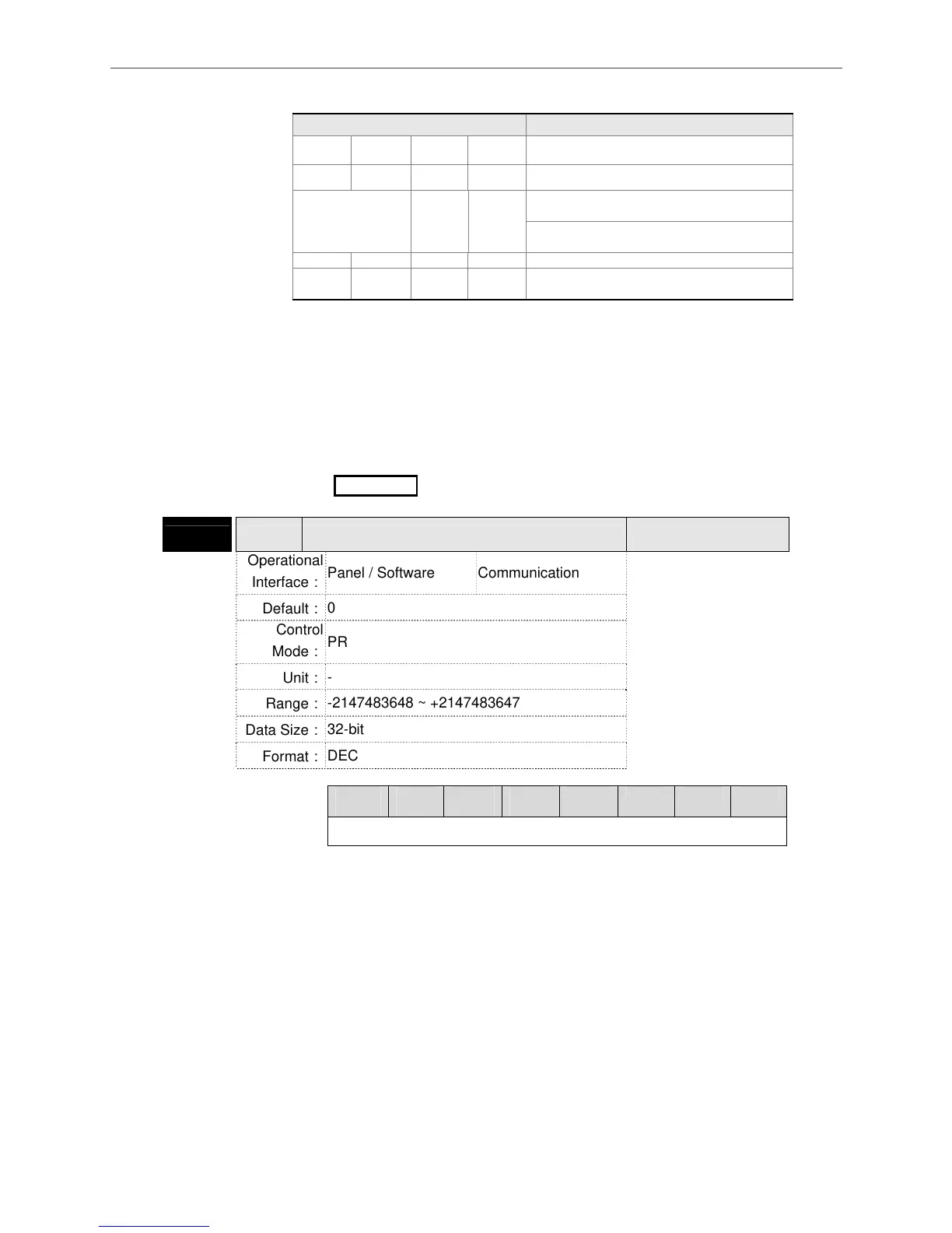
P6-03 PDAT1 PATH# 1 Data
Address: 0606H
0607H
Operational
Interface:
Panel / Software Communication
Related Section:
7.10
Default:
0
Control
Mode:
PR
Unit:
-
Range:
-2147483648 ~ +2147483647
Data Size:
32-bit
Format:
DEC
Settings:
PATH# 1 Data
.31 ~
28
.27 ~
24
.23
~20
.19 ~
16
.15 ~
12
11 ~ 8 7 ~ 4 3 ~ 0
DATA (32-bit)
Property of P6-02; P6-03 corresponds to the target position of P6-02 or
jump to PATH_NO.
Note: PATH (procedure)
The unit of position data in PR mode is PUU. PUU is the position unit that encoder’s original
pulse number being converted with E-gear ratio through the servo drive. For example, the
resolution of ASDA-A2 is 1280000 pulse/rev, if E-gear ratio is 128:10 (P1-44=128 / P1-45=10),
the PUU for an ASDA-A2 motor to make one full rotation is 1280000*(10/128) = 100000 PUU.
The best thing about using this method is that the unit of commands, errors, and feedback are
the same, which means no conversion is needed here and it is easy to be read and compared.

 Loading...


