BASIC OPERATIONS
77144 Issue 8 August 2009 43
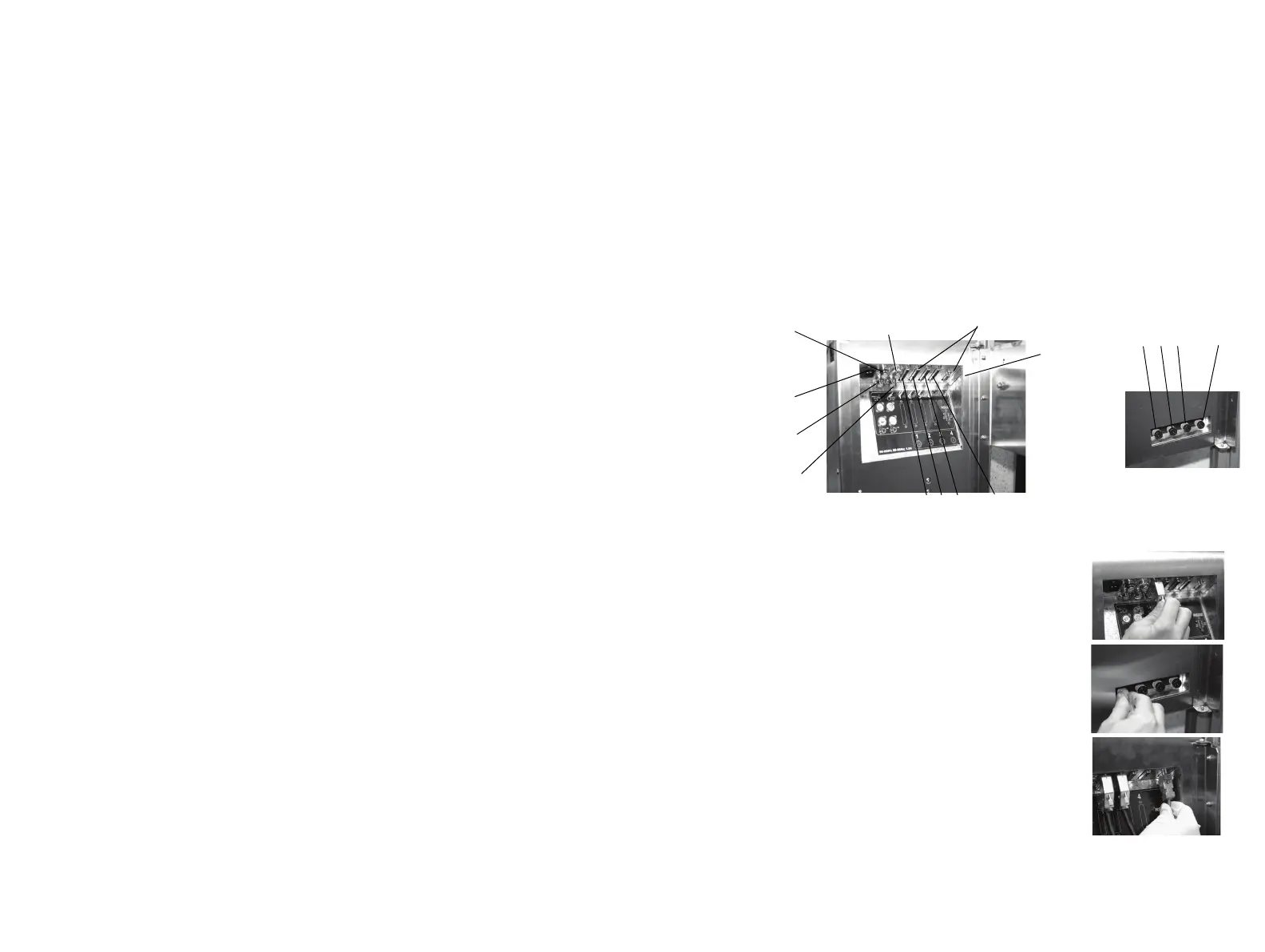
INTERCONNECTIONS
Base Unit
CAUTION: Ensure that Control Unit connector 1 and ink connector 1 are
connected to control unit 1 and so on.
(1) The connections on the back of the control unit are for power, 4 x Control
unit connections, 1 x product sensor, 1 x shaft encoder, 2 x beacons (1 for
bottle out, 1 for ink out) and 1 x RS232 connection, there are also 4 x ink
connections. The control unit and ink connections relate to the 4 control
units that can be connected to the base. All connections should be checked
and maintained to ensure that the unit remains in good working order.
(2) Connect the 25-way connector(s) from the
control unit(s) to the base unit.
(3) Remove the blanking plug from the ink
connectors and connect the ink tube(s)
from the control unit(s) to the base unit.
(4) If required (e.g. for downloading messages),
connect the RS232 connection. This only
communicates to head 1, see “Options” on
page 85 for communication to multiple
heads.
Control Unit
Connectors
RS232
Product
Detector
Shaft
Encoder
Power
Connector
Ink Out
Beacon
Bottle Out
Beacon
Base Unit
Ink Connectors
Base Unit Connectors
To control Unit
1, 2, 3 and 4
To control Unit 1, 2, 3 and 4
 Loading...


