BASIC OPERATIONS
77144 Issue 8 August 2009 45
Control Units
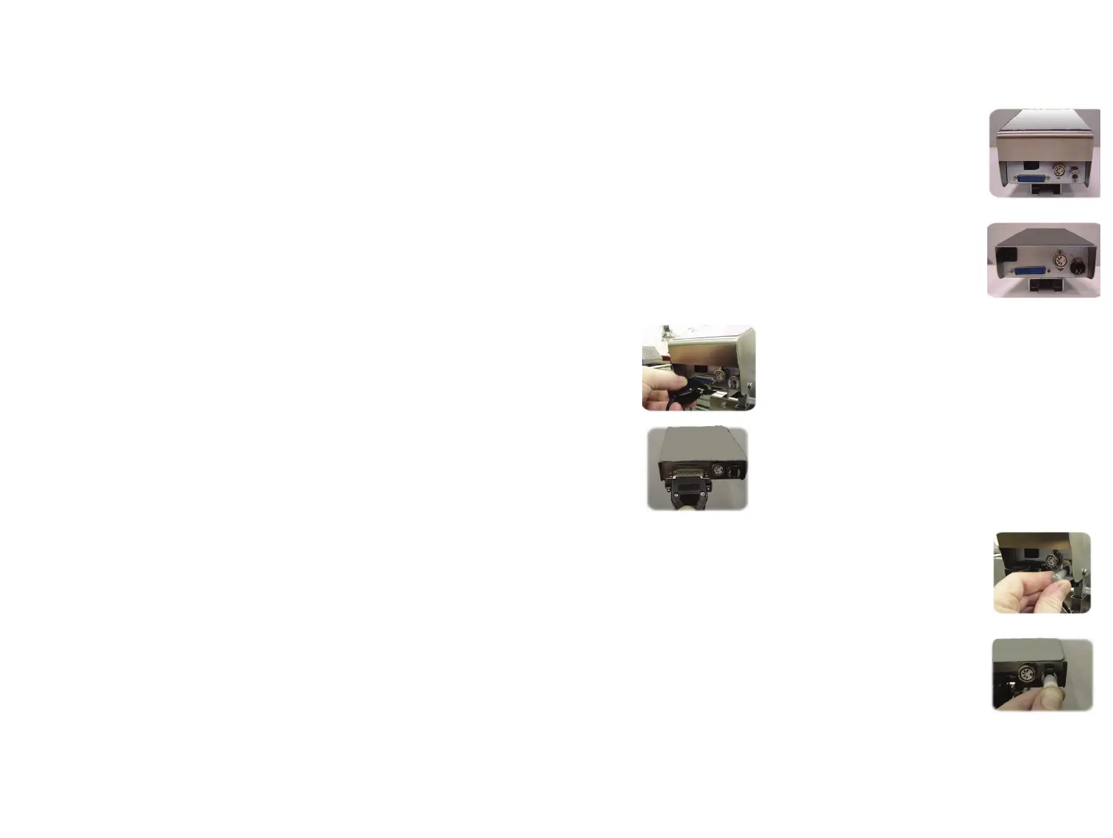
(1) The four connections on the back of the control unit
are the power, ink, external sensor and ethernet
connections. These connections should always be
checked and maintained to ensure that the unit
remains in good working order.
(2) The black power cable, from the base unit, is connected
to the power connection port and is secured in position
by two fixing screws. To unplug the connector ensure
these screws are unfastened.
(3) To connect the ink line, use the quick release (QR)
connector on the end of the translucent plastic tube,
running from the bottom rear of the base unit. The
QR connector must be pushed into the female
connection port on the back of the control unit head
until it clicks into place.
C6000(i), C6000v
C3000 & C1000
C6000(i), C6000v
C3000 & C1000
C6000(i), C6000v
C3000 & C1000
 Loading...


