DV11
Operation and Maintenance
134
Common Rail Fuel-injection System
Printed in Mar. 2005 PS-MMA0608-E1A
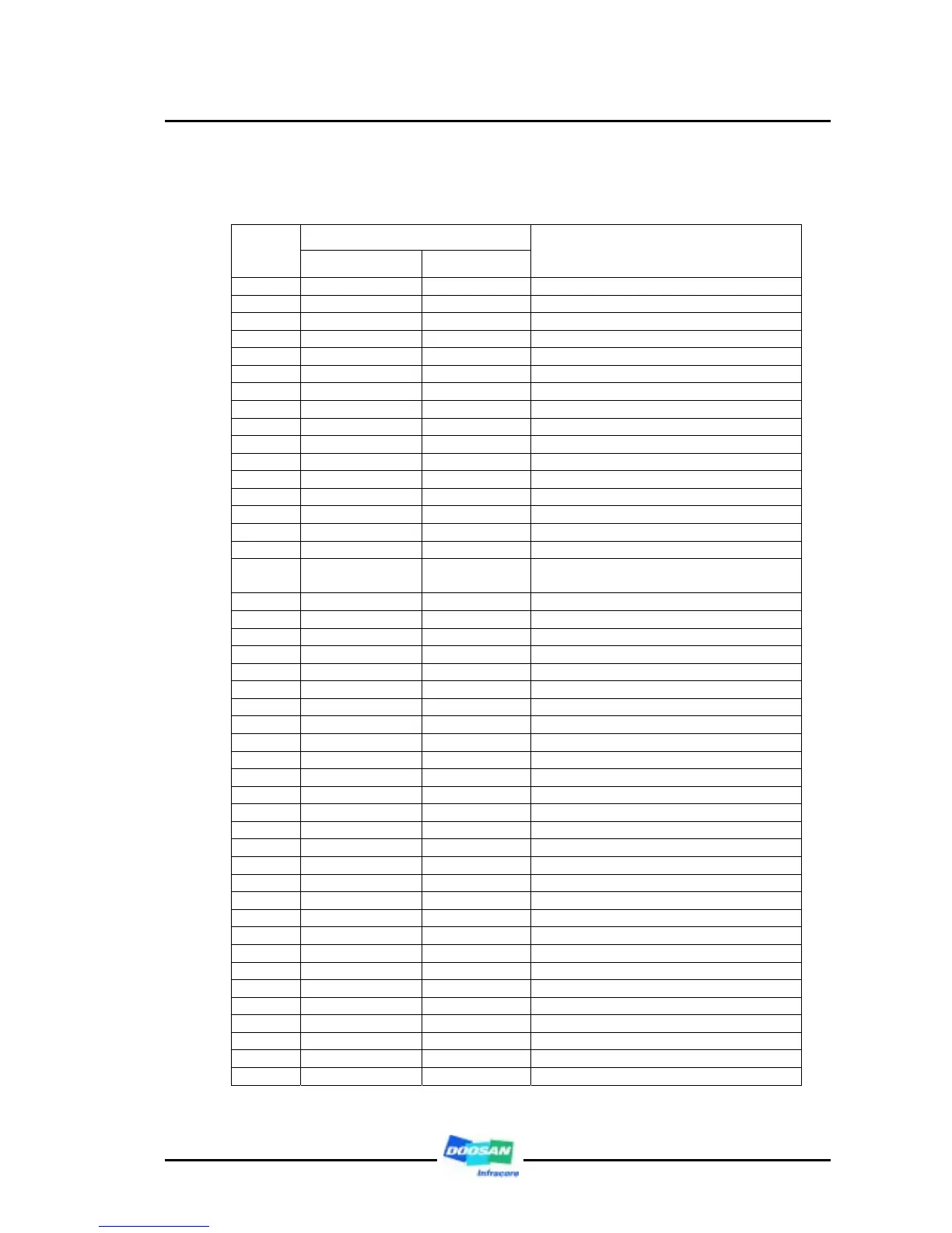
3.5.5. Electrical Control Unit
Signal
Pin no.
BOSCH DOOSAN
Part name
1.01 V_V_BAT+1 V_V_BAT+1 Battery plus (+24V)
1.03 G_G_BAT-1 G_G_BAT-1 Battery minus (-24V)
1.04 G_G_RH01 G_G_RH01 Ground (-24V)
1.07 V_V_BAT+2 V_V_BAT+2 Battery minus (+24V)
1.08 O_V_RL O_V_RL ECU Battery voltage (+24V)
1.09 G_G_BAT-2 G_G_BAT-2 Battery minus (-24V)
1.11 O_S_EBR1 O_S_RH04 Engine brake 1 power output
1.12 V_V_BAT+3 V_V_BAT+3 Battery plus (+24V)
1.13 V_V_BAT+4 V_V_BAT+4 Battery plus (+24V)
1.14 G_G_BAT-3 G_G_BAT-3 Battery minus (-24V)
1.15 G_G_BAT-4 G_G_BAT-4 Battery minus (-24V)
1.16 O_S_CSHRLY O_S_RH01 Air heater relay
1.17 O_S_EBR2 O_S_RH02 Engine brake 2 power output
1.19 G_R_DIG G_R_DIG Digital ground
1.22 I_S_PTO I_S_DIG14 Power take off (PTO) signal
1.27 I_S_DIA I_S_DIG15 Diagnostic operation switch
1.28 O_V_DIA O_V_RL06
ECU Battery voltage (+24V)
for diagnostic lamp operation
1.29 O_S_CSLP O_S_RL02 Cold starting lamp
1.31 B_D_ISOK B_D_ISOK ISO K-line
1.32 G_R_TL G_R_PAS06 Torque limitation ground
1.33 G_C_CAN2 G_C_CAN2 ECU network 2 , shield
1.34 B_D_CANL2 B_D_CANL2 ECU network 2 , low
1.35 B_D_CANH2 B_D_CANH2 ECU network 2 , high
1.38 I_S_CRCMOD I_S_DIG13 Cruise control mode switch
1.39 I_S_T15 I_S_T15 Key switch (Terminal 15)
1.40 I_S_EBR1 I_S_DIG10 Engine brake switch 1 signal
1.41 I_S_EBR2 I_S_DIG17 Engine brake switch 2 signal
1.45 I_S_STP I_S_DIG21 Engine stop switch signal
1.48 O_F_DA02 O_F_DA02 #1 Injector operation – frequency
1.49 O_F_VSS O_F_DA01 Vehicle speed sensor output signal
1.50 G_R_RMTC G_R_ACT09 Remote control, sensor ground
1.51 G_C_CAN1 G_C_CAN1 ECU network 1, shield
1.52 B_D_CANL1 B_D_CANL1 ECU network 1, low
1.53 B_D_CANH1 B_D_CANH1 ECU network 1, high
1.54 G_R_FSS G_R_DF06 Fan speed sensor ground
1.55 V_V_5VAPP V_V_5VSS4A Accelerator pedal sensor supply (5V)
1.56 G_R_VSS G_R_DF04 Vehicle speed sensor ground
1.59 I_S_CRCRES I_S_DIG06 Cruise control – resume
1.60 I_S_CRCOFF I_S_DIG09 Cruise control – off
1.61 I_S_CRCNEG I_S_DIG08 Cruise control – set/decelerate
1.62 I_S_CONV I_S_DIG05 Clutch switch (torque converter)
1.64 O_S_DIA O_S_RL06 Diagnostic lamp
1.66 O_F_CRCVSL O_F_DA03 Variable speed limitation output signal
1.67 V_V_5VFSS V_V_5VSS3A Fan speed sensor supply (5V)
1.68 V_V_5VRMTC V_V_5VSS1C Remote control supply (5V)
 Loading...