FLEX-6000 Signature Series - SmartSDR for Windows Software User’s Guide
Page 177
Copyright 2018 FlexRadio Systems. All Rights Reserved.
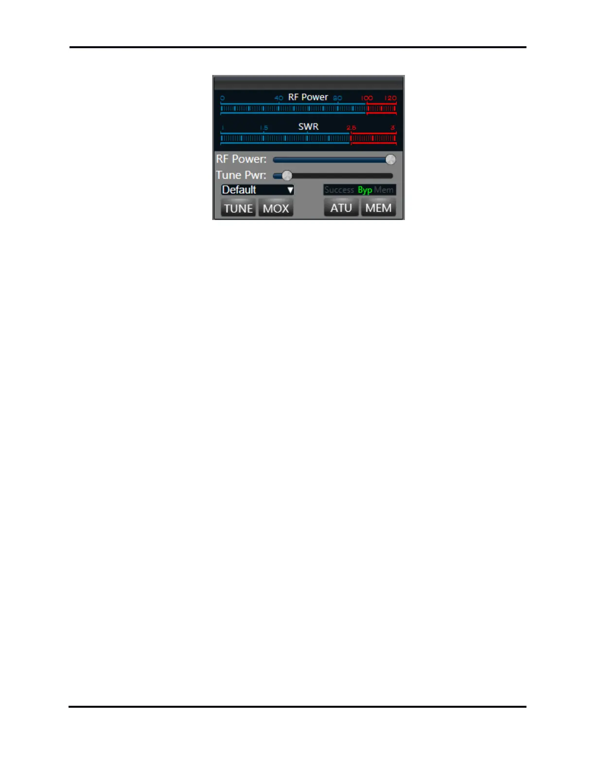
37.7.1 RF Power / ATU Control Panel
• RF Power bar meter: This meter is an indication of the peak RF power being transmitted
• SWR bar meter: While transmitting, the SWR meter will measure the ratio of peak voltage
on the minimum amplitude of voltage of standing wave, or VSWR. This is an indication of
the radiated RF power efficiency. The radio software automatically folds back transmitter
power so that the power reflected by the antenna does not exceed 25 watts. This feature
protects the Power Amplifier but should not be relied upon when operating with a
mismatched antenna.
• RF Power slider control: Moving the slider control to the right increases the RF power
output. A value of 0 will not produce any RF output. The scale, from 0 – 100 approximates
RF output wattage. If the Max Power in the Radio Setup->Transmit tab has been set for a
value lower than 100, the slider will not progress beyond that limit.
• Tune Pwr Slider: The Tune Pwr (Power) slider control determines the power output level
when TUNE is enabled. Moving the slider to the right increases the RF power output. A
value of 0 will not produce any RF output. The scale, from 0 – 100 approximates RF output
wattage.
• Transmit Profile Drop-down: This drop-down allows the user to quickly toggle between
different Transmit profiles that have previously been created.
• TUNE button: Clicking this button will cause the transmitter to output a sinusoidal tone at
low wattage (10 watts by default) for running external automatic antenna tuners and
amplifiers. While TUNE is enabled, the output wattage can be adjusted using the RF Power
slider control. When the TUNE button is the last to be pressed, the space bar can be used
to toggle the TUNE state.
• MOX button: Clicking this button will key the transmitter. Clicking the MOX button while
enabled will turn off or unkey the transmitter. When the MOX button is the last to be
pressed, the space bar can be used to toggle the MOX state.
• ATU button: Clicking this button will initiate a tuning sequence by the internal Antenna
Tuning Unit (ATU). If successful, the button will stay illuminated and the Success message
will be displayed in the ATU Tune Operation Indicator. If the tuning operation fails to find a
better impedance match, the ATU button will turn off, and either the Success or Byp
message will appear in the ATU Tune Operation Indicator.
• MEM button: When illuminated, this button turns on the ATU memories.
• ATU Tune Operation Indicator: This annunciator display will indicate the result of an ATU
tuning operation, where the possible outcomes are Success, Byp and Mem.

 Loading...