CHAPTER 8: MODBUS FUNCTIONS FUNCTION CODE 04H
SR3 SERIES PROTECTIVE RELAY PLATFORM – COMMUNICATIONS GUIDE 8-3
Function Code 04H
Modbus Implementation: Read Input Registers
3 Series relay implementation: Read Actual Values
For the 3 Series relay implementation of Modbus, this function code can be used to read
any actual values (“input registers”). Input registers are 16 bit (two byte) values transmitted
high order byte first. Thus all 3 Series relay
Actual Values are sent as two bytes. The
maximum number of registers that can be read in one transmission is 125.
The slave response to this function code is the slave address, function code, a count of the
data bytes to follow, the data itself and the CRC. Each data item is sent as a two byte
number with the high order byte sent first.
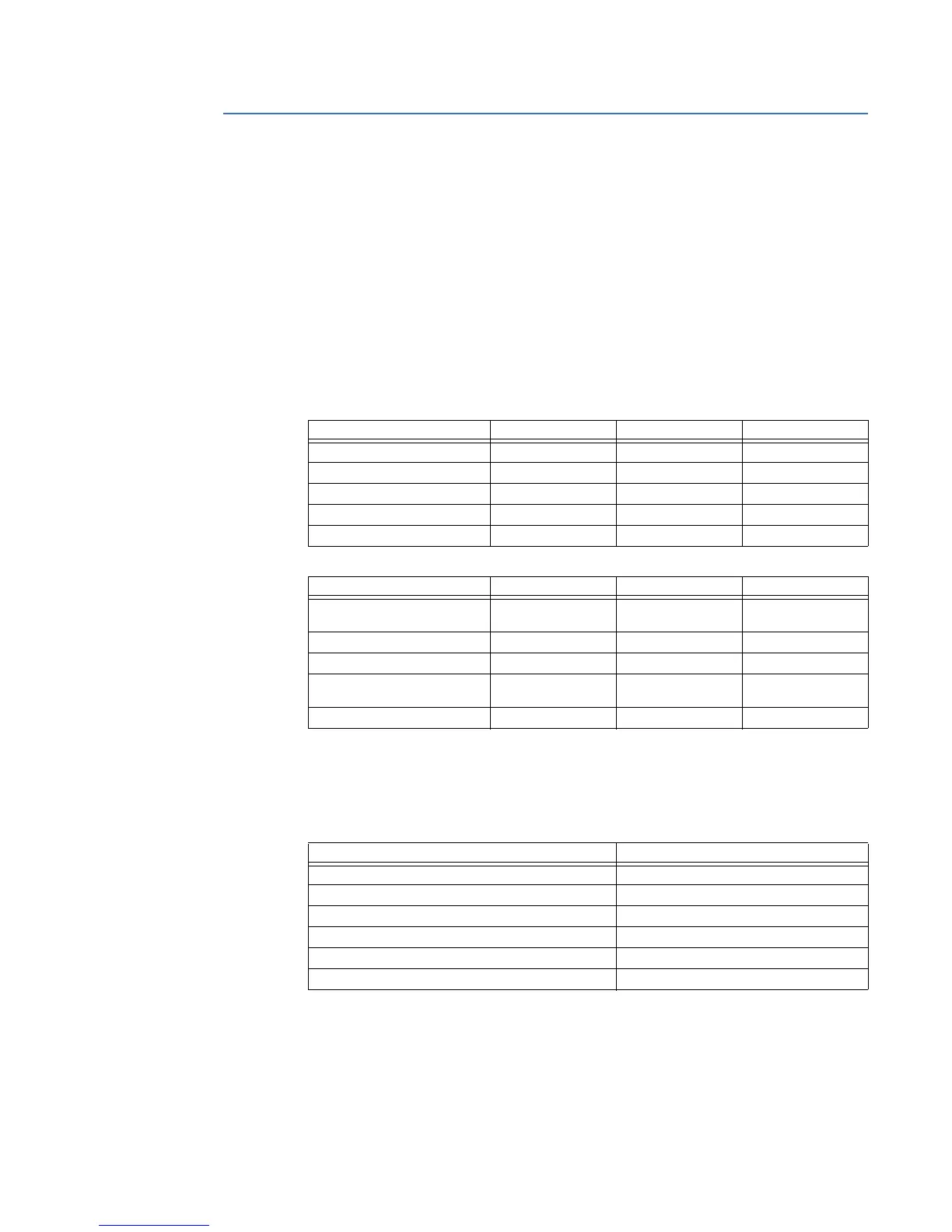
For example, request slave 17 to respond with 1 register starting at address 0008. For this
example the value in this register (0008) is 0000.
Table 8-2: MASTER/SLAVE PACKET FORMAT FOR FUNCTION CODE 04H
Query:
The query message specifies the starting register and quantity of registers to be read.
Registers are addressed starting at zero: registers 1 to 16 are addressed as 0 to 15.
Here is an example of a request to read register 30305 from slave device 254:
Response:
The register data in the response message are packed as two bytes per register, with the
binary contents right justified within each byte. For each register, the first byte contains
the high order bits and the second contains the low order bits.
MASTER TRANSMISSION BYTES EXAMPLE DESCRIPTION
SLAVE ADDRESS 1 11 message for slave 17
FUNCTION CODE 1 04 read registers
DATA STARTING ADDRESS 2 00 08 data starting at 0008
NUMBER OF ACTUAL VALUES 2 00 01 1 register = 2 bytes
CRC 2 B2 98 CRC error code
SLAVE RESPONSE BYTES EXAMPLE DESCRIPTION
SLAVE ADDRESS 1 11 message from slave
17
FUNCTION CODE 1 04 read registers
BYTE COUNT 1 02 1 register = 2 bytes
DATA (see definition above) 2 00 00 value in address
0008
CRC 2 78 F3 CRC error code
Field Name Hex
Slave Address FE
Function 04
Starting Address Hi 01
Starting Address Lo 30
No. of Points Hi 00
No. of Points Lo 01

 Loading...


