EasyManua.ls Logo

GE 350 User Manual

GE 350
786 pages
To Next Page IconTo Next Page
To Previous Page IconTo Previous Page
Page #152 background imageLoading...
Page #152 background image
8-4 SR3 SERIES PROTECTIVE RELAY PLATFORM – COMMUNICATIONS GUIDE
FUNCTION CODE 05H CHAPTER 8: MODBUS FUNCTIONS
Function Code 05H
Modbus Implementation: Force Single Coil
3 Series relay Implementation: Execute Operation
This function code allows the master to request a 3 Series relay to perform specific
command operations.
For example, to request slave 17 to execute operation code 1 (reset), we have the following
master/slave packet format:
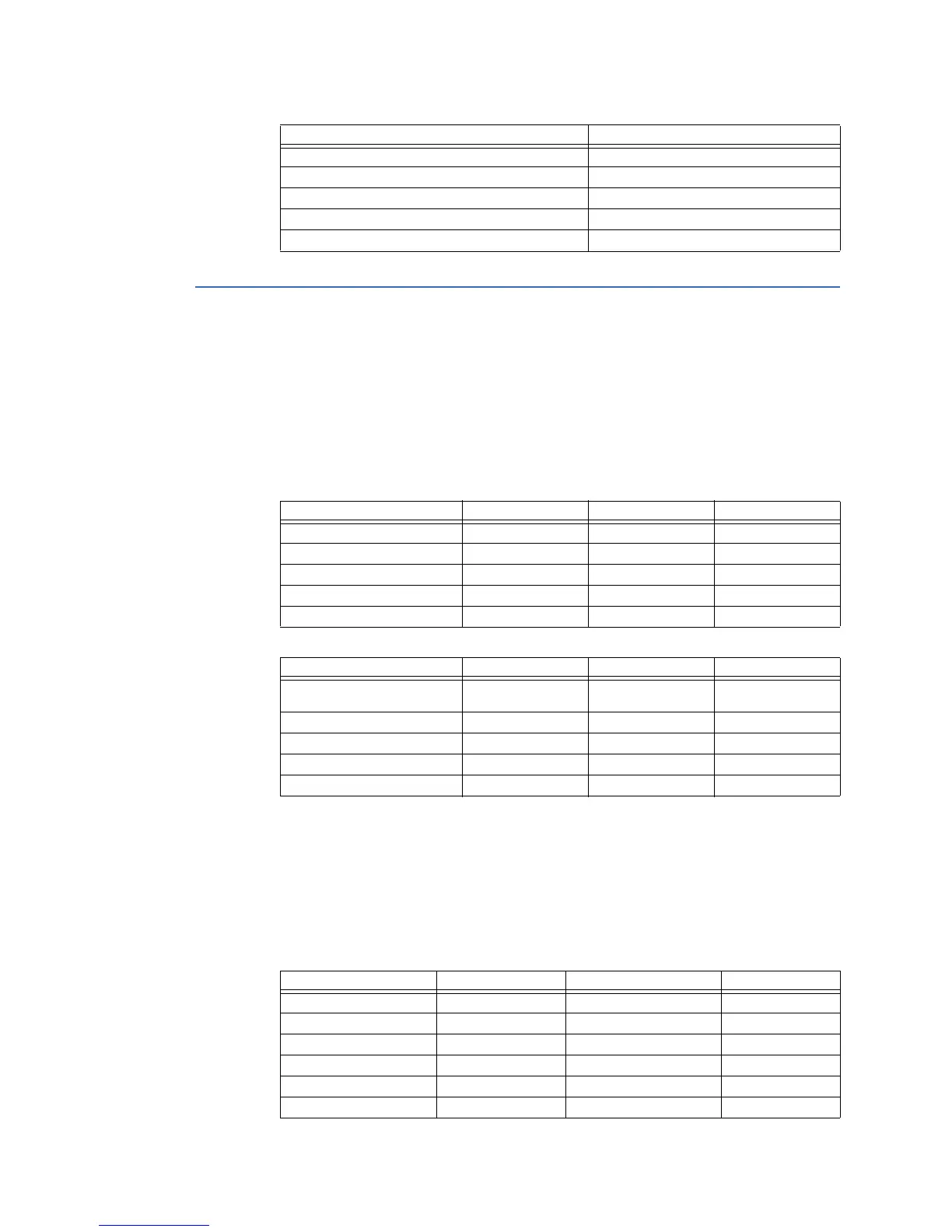
Table 8-3: MASTER/SLAVE PACKET FORMAT FOR FUNCTION CODE 05H
Forces a single coil (0X reference) to either ON or OFF.
The query message specifies the coil reference to be forced. Coils are addressed starting at
zero: coil 1 is addressed as 0.
The requested ON/OFF state is specified by a constant in the query data field.
A value of FF 00 hex requests the coil to be ON. A value of 00 00 requests it to be OFF. All
other values are illegal and will not affect the coil.
Force Virtual Inputs:
Field Name Hex
Slave Address FE
Function 04
Byte Count 02
Data Hi (Register 30305) 80
Data Lo (Register 30305) 80
MASTER TRANSMISSION BYTES EXAMPLE DESCRIPTION
SLAVE ADDRESS 1 11 message for slave 17
FUNCTION CODE 1 05 execute operation
OPERATION CODE 2 00 01 operation code 1
CODE VALUE 2 FF 00 perform function
CRC 2 DF 6A CRC error code
SLAVE RESPONSE BYTES EXAMPLE DESCRIPTION
SLAVE ADDRESS 1 11 message from slave
17
FUNCTION CODE 1 05 execute operation
OPERATION CODE 2 00 01 operation code 1
CODE VALUE 2 FF 00 perform function
CRC 2 DF 6A CRC error code
Description Coil Address (HEX) Description Coil Address (HEX)
Virtual Input 1 0x1000 Virtual Input 17 0x1010
Virtual Input 2 0x1001 Virtual Input 18 0x1011
Virtual Input 3 0x1002 Virtual Input 19 0x1012
Virtual Input 4 0x1003 Virtual Input 20 0x1013
Virtual Input 5 0x1004 Virtual Input 21 0x1014

Table of Contents

Question and Answer IconNeed help?

Do you have a question about the GE 350 and is the answer not in the manual?

GE 350 Specifications

General IconGeneral
BrandGE
Model350
CategoryProtection Device
LanguageEnglish

Summary

SR3 Series Protective Relay Platform

1. INTRODUCTION

Overview of the SR3 Protective Relay Platform and its communication capabilities.

2. RS485 INTERFACE

Details on the RS485 hardware and electrical interface for serial communication.

3. ETHERNET INTERFACE

Information on the Ethernet option for the 3 Series relay, including redundancy and protocols.

4. 3 SERIES IEC61850 GOOSE

Implementation and configuration of IEC61850 GOOSE messaging for relay communication.

5. 350 OPC–UA COMMUNICATION STANDARD

Details on the OPC-UA implementation and architecture for the 350 relay.

6. USB INTERFACE

Information on using the USB port for Modbus protocol communication with the 3 Series relay.

7. 350 TIME PROTOCOLS

Details on time synchronization protocols like PTP and Real-Time Clock for the 350 relay.

8. MODBUS FUNCTIONS

Explanation of supported Modbus function codes and their implementation in the 3 Series relay.

9. USING THE MODBUS USER MAP

Guidance on utilizing the Modbus User Map feature for remapping data records.

10. 339 MODBUS MEMORY MAP AND FORMAT CODES

Comprehensive details on the Modbus memory map and format codes for the 339 relay.

11. 345 MODBUS MEMORY MAP AND FORMAT CODES

Detailed Modbus memory map and format codes specific to the 345 relay.

12. 350 MODBUS MEMORY MAP AND FORMAT CODES

Comprehensive Modbus memory map and format codes for the 350 relay.

Appendix A: IEC 61850 Implementation Details

Technical details regarding IEC 61850 interface implementation in the 3 Series Family.

Appendix B: Warranty and Revision History

Information on product warranty and manual revision history.

Related product manuals