3-22 SR3 SERIES PROTECTIVE RELAY PLATFORM – COMMUNICATIONS GUIDE
IEC60870-5-104 PROTOCOL CHAPTER 3: ETHERNET INTERFACE
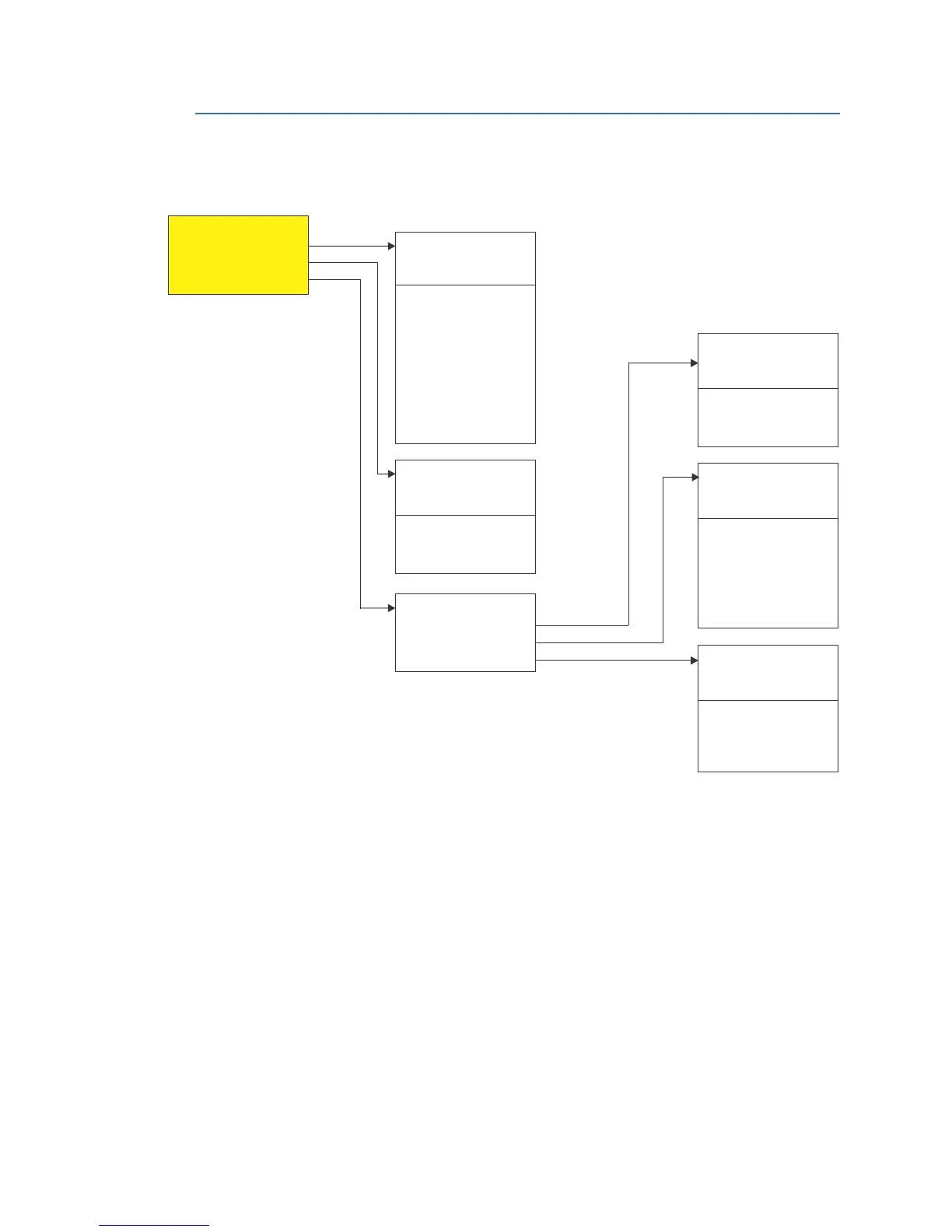
IEC60870-5-104 protocol
Figure 3-7: IEC 60870-5-104 protocol menu
IEC 60870-5-104 interoperability
This document is adapted from the IEC 60870-5-104 standard. For this section the boxes
indicate the following: ⊠ – used in the standard direction; □– not used.
IEC 60870-5-104 Interoperability Document
1. System or device:
□ System definition.
□ Controlling station definition (master).
⊠ Controlled station definition (slave).
2. Application layer:
2.1. Transmission mode for application data:
Mode 1 (least significant octet first), as defined in Clause 4.10 of IEC 60870-5-4, is
used exclusively in this companion standard.
2.2. Common address of ADSU:
⊠ Two octets.
2.3. Information object address:
104 BINARY INPUTS
POINT 0
POINT 1
...
POINT 63
ٕ
S1 104 GENERAL
FUNCTION
TCP PORT
SLAVE ADDRESS
CYCLIC DATA PERIOD
TCP CONN. TIMEOUT
OBJ INFO ADDR BIN
OBJ INFO ADDR ALOG
OBJ INFO ADDR CNTR
OBJ INFO ADDR CMD
FAULT REP MAPPING
ٕ
898794A2.cdr
S1 104 POINT LIST
BINARY INPUTS
ANALOG INPUTS
BINARY OUTPUTS
S1 60870-5-104
GENERAL
CLIENT ADDRESS
POINT LIST
104 ANALOG INPUTS
POINT 0 ENTRY
POINT 0 SCALE FCTR
POINT 0 DEADBAND
...
POINT 31 ENTRY
POINT 31 SCALE FCTR
POINT 31 DEADBAND
ٕ
S1 104 CLIENT ADDRESS
CLIENT ADDRESS 1
CLIENT ADDRESS 2
...
CLIENT ADDRESS 5
ٕ
.
.
.
.
104 BINARY OUTPUTS
POINT 0 ON
POINT 0 OFF
...
POINT 15 ON
POINT 15 OFF
ٕ
.
.
.
.

 Loading...


