2-14 SR3 SERIES PROTECTIVE RELAY PLATFORM – COMMUNICATIONS GUIDE
DNP PROTOCOL SETTINGS CHAPTER 2: RS485 INTERFACE
DNP general
Default variations for Object 1, 2 , 20 , 21 , 22 , 23 , 30 and Object 32 will be set by settings
and returned for the object in a response when no specific variation is specified in a Master
request.
Any change in the state of any binary point causes the generation of an event, and
consequently, if configured, an unsolicited response. Alternatively it is returned when the
Master asks for it. The same behavior will be seen when an analog value changes by more
than its configured deadband limit. There can be up to 3 masters in total, but only one
Serial Master.
The following Default Classes will be fixed for the different blocks of data:
Binary Input Points Default Class = 1
Analog Input Point Default Class = 2
Counters Default Class = 3
Each Data Point Class can be changed by protocol function code 22 in volatile mode. If a
restart is performed, the new values will be lost.
DNP Object 34 points can be used to change deadband values from the default for each
individual DNP Analog Input point. These new deadbands will be maintained such that in
the case of a relay restart, the values are not lost.
For the 350 and 339 relays, one Binary Counter has been hardcoded such that no option
can be modified by setting:
• Total_Number_of_Trips
Requests for Object 20 (Binary Counters), Object 21 (Frozen Counters), and Object 22
(Counter Change Events) must be accepted.
Function codes “Immediate Freeze”, “Freeze and Clear” etc. are accepted as well.
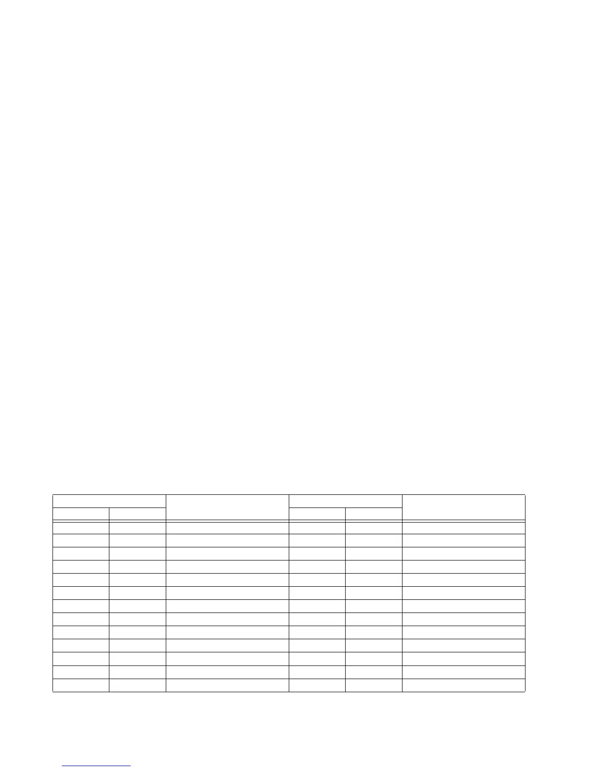
The FAULT REPORT MAPPING IN DNP/104 setpoint may be set to a value of "Disabled" or
"Enabled". When "Disabled", only the configurable Analog Input points are available
beginning at point index 0.When "Enabled", the Fault Report Values are assigned from
point 0 to 32 in the 339 and 350 relays, and from 0 to 38 in the 345 relay, with the
configurable Analog Inputs following the point numbers.
To support existing SCADA hardware not capable of 32-bit data reads, the upper and lower
16-bit portions of the fault report time and date values have been assigned to separate
points. To read a date or time, it is necessary to read both the upper and lower 16-bit
portions, concatenate these two values to form a 32-bit value and interpret the result in
the format associated with the point.
Fault Report Mapping 350 and 339 Fault Report Mapping 345
Disabled Enabled Disabled Enabled
- 0 Fault Report Date Upper 16 - 0 Fault Report Date Upper 16
- 1 Fault Report Date Lower 16 - 1 Fault Report Date Lower 16
- 2 Fault Report Time Upper 16 - 2 Fault Report Time Upper 16
- 3 Fault Report Time Lower 16 - 3 Fault Report Time Lower 16
- 4 Fault Report Fault Type - 4 Fault Report Fault Type
- 5 Fault Report Ia - 5 Fault Report Ia
- 6 Fault Report Ia Angle - 6 Fault Report Ia Angle
- 7 Fault Report Ib - 7 Fault Report Ib
- 8 Fault Report Ib Angle - 8 Fault Report Ib Angle
- 9 Fault Report Ic - 9 Fault Report Ic
- 10 Fault Report Ic Angle - 10 Fault Report Ic Angle
- 11 Fault Report Ig - 11 Fault Report Ig
- 12 Fault Report Ig Angle - 12 Fault Report Ig Angle

 Loading...


