CHAPTER 3: ETHERNET INTERFACE MODBUS TCP/IP
SR3 SERIES PROTECTIVE RELAY PLATFORM – COMMUNICATIONS GUIDE 3-9
Response:
Exception and error responses
One data frame of an asynchronous transmission to or from a 3 Series relay typically
consists of 1 start bit, 8 data bits, and 1 stop bit. This produces a 10 bit data frame. This is
important for transmission through modems at high bit rates.
Request response sequence
A complete request/response sequence consists of the following bytes (transmitted as
separate data frames):
Master Request Transmission:
SLAVE ADDRESS: 1 byte
FUNCTION CODE: 1 byte
DATA: variable number of bytes depending on FUNCTION CODE
Slave Response Transmission:
SLAVE ADDRESS: 1 byte
FUNCTION CODE: 1 byte
DATA: variable number of bytes depending on FUNCTION CODE
SLAVE ADDRESS: This is the first byte of every transmission. This byte represents the user-
assigned address of the slave device that is to receive the message sent by the master.
Each slave device must be assigned a unique address and only the addressed slave will
respond to a transmission that starts with its address. In a master request transmission the
SLAVE ADDRESS represents the address of the slave to which the request is being sent. In a
slave response transmission the SLAVE ADDRESS represents the address of the slave that is
sending the response.
FUNCTION CODE: This is the second byte of every transmission. Modbus defines function
codes of 1 to 127.
DATA: This will be a variable number of bytes depending on the FUNCTION CODE. This may
be Actual Values, Setpoints, or addresses sent by the master to the slave or by the slave to
the master.
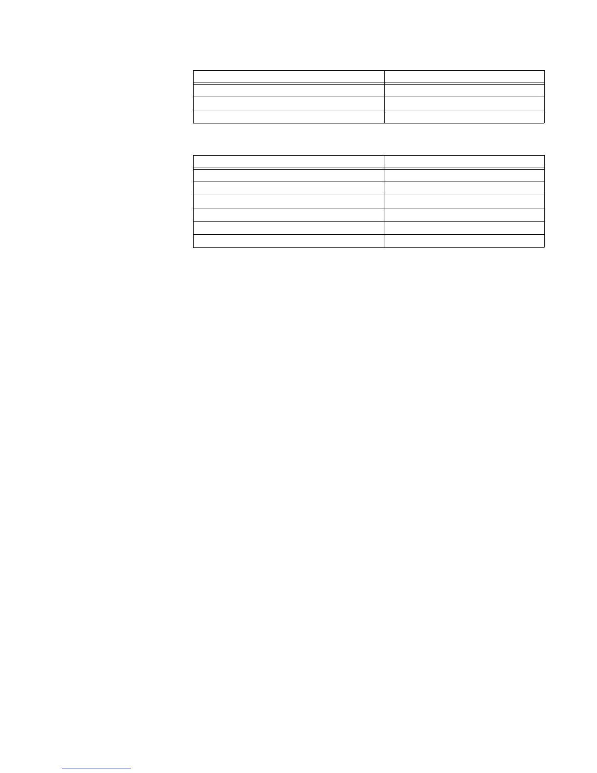
Byte Count 04 02
Data Hi 00
Data Lo 01
Field Name Hex
Slave Address FE
Function 43
Starting Address Hi 09
Starting Address Lo C1
No. of Registers Hi 00
No. of Registers Lo 01
Field Name Hex

 Loading...


