EasyManua.ls Logo

GE 350 User Manual

GE 350
786 pages
To Next Page IconTo Next Page
To Previous Page IconTo Previous Page
Page #161 background imageLoading...
Page #161 background image
CHAPTER 8: MODBUS FUNCTIONS FUNCTION CODE 10H
SR3 SERIES PROTECTIVE RELAY PLATFORM – COMMUNICATIONS GUIDE 8-13
Performing Commands Using Function Code 10H
Commands can be performed using function code 16 (10H) as well as function code 5.
When using FUNCTION CODE 16, the Command Function register must be written with a
value of 5. The Command Operation register must be written with a valid command
operation number. The Command Data registers must be written with valid data; this is
dependent upon the command operation.
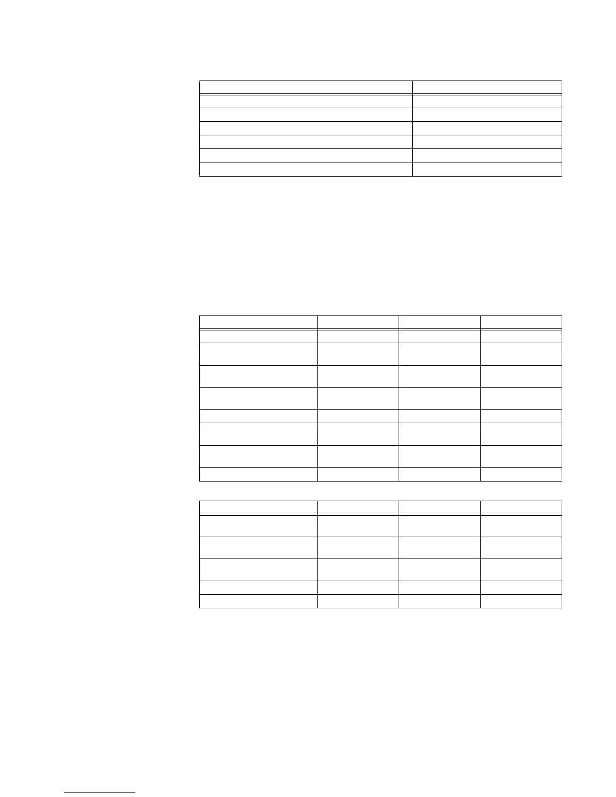
For example, consider a request for slave 17 to perform command operation 1 (RESET): The
master/slave packets have the following format:
Table 8-9: MASTER/SLAVE PACKET FORMAT FOR PERFORMING COMMANDS
Field Name Hex
Slave Address FE
Function 10
Starting Address Hi 0F
Starting Address Lo 0A
No. of Registers Hi 00
No. of Registers Lo 02
MASTER TRANSMISSION BYTES EXAMPLE DESCRIPTION
SLAVE ADDRESS 1 11 message for slave 17
FUNCTION CODE 1 10 store multiple
setpoints
DATA STARTING ADDRESS 2 00 80 setpoint address 00
80
NUMBER OF SETPOINTS 2 00 02 2 setpoints = 4 bytes
total
BYTE COUNT 1 04 4 bytes of data
DATA 1 2 00 05 data for address 00
80
DATA 2 2 00 01 data for address 00
81
CRC 2 7E CE CRC error code
SLAVE RESPONSE BYTES EXAMPLE DESCRIPTION
SLAVE ADDRESS 1 11 message from slave
17
FUNCTION CODE 1 10 store multiple
setpoints
DATA STARTING ADDRESS 2 00 80 setpoint address 00
80
NUMBER OF SETPOINTS 2 00 02 2 setpoints
CRC 2 42 B0 CRC error code

Table of Contents

Question and Answer IconNeed help?

Do you have a question about the GE 350 and is the answer not in the manual?

GE 350 Specifications

General IconGeneral
BrandGE
Model350
CategoryProtection Device
LanguageEnglish

Summary

SR3 Series Protective Relay Platform

1. INTRODUCTION

Overview of the SR3 Protective Relay Platform and its communication capabilities.

2. RS485 INTERFACE

Details on the RS485 hardware and electrical interface for serial communication.

3. ETHERNET INTERFACE

Information on the Ethernet option for the 3 Series relay, including redundancy and protocols.

4. 3 SERIES IEC61850 GOOSE

Implementation and configuration of IEC61850 GOOSE messaging for relay communication.

5. 350 OPC–UA COMMUNICATION STANDARD

Details on the OPC-UA implementation and architecture for the 350 relay.

6. USB INTERFACE

Information on using the USB port for Modbus protocol communication with the 3 Series relay.

7. 350 TIME PROTOCOLS

Details on time synchronization protocols like PTP and Real-Time Clock for the 350 relay.

8. MODBUS FUNCTIONS

Explanation of supported Modbus function codes and their implementation in the 3 Series relay.

9. USING THE MODBUS USER MAP

Guidance on utilizing the Modbus User Map feature for remapping data records.

10. 339 MODBUS MEMORY MAP AND FORMAT CODES

Comprehensive details on the Modbus memory map and format codes for the 339 relay.

11. 345 MODBUS MEMORY MAP AND FORMAT CODES

Detailed Modbus memory map and format codes specific to the 345 relay.

12. 350 MODBUS MEMORY MAP AND FORMAT CODES

Comprehensive Modbus memory map and format codes for the 350 relay.

Appendix A: IEC 61850 Implementation Details

Technical details regarding IEC 61850 interface implementation in the 3 Series Family.

Appendix B: Warranty and Revision History

Information on product warranty and manual revision history.

Related product manuals