GE Multilin L60 Line Phase Comparison System 5-43
5 SETTINGS 5.2 PRODUCT SETUP
5
Refer to the Control of setting groups example in the Control elements section of this chapter for group activation.
5.2.11 USER-PROGRAMMABLE SELF TESTS
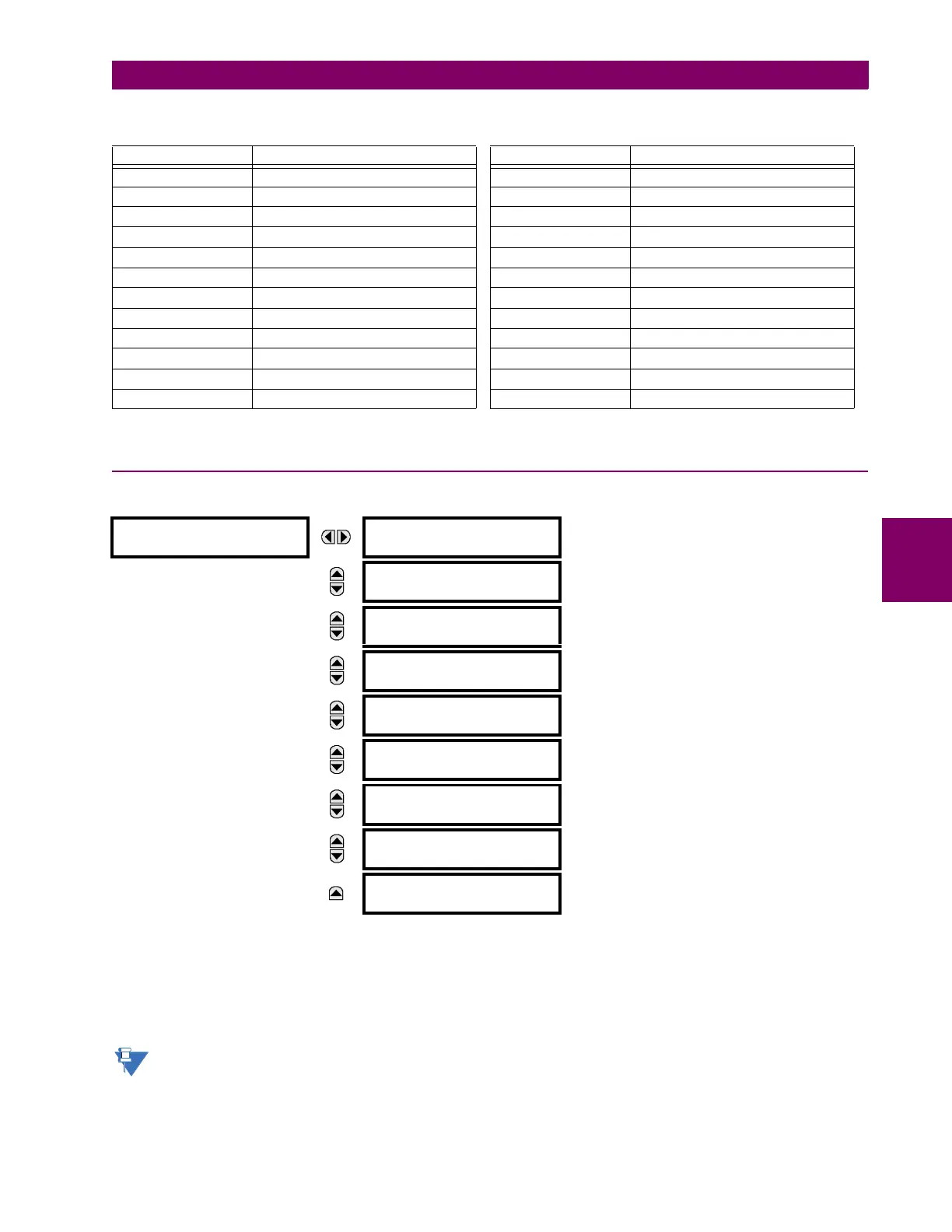
PATH: SETTINGS Ö PRODUCT SETUP ÖØ USER-PROGRAMMABLE SELF TESTS
All major self-test alarms are reported automatically with their corresponding FlexLogic™ operands, events, and targets.
Most of the minor alarms can be disabled if desired.
When in the “Disabled” mode, minor alarms will not assert a FlexLogic™ operand, write to the event recorder, or display
target messages. Moreover, they will not trigger the
ANY MINOR ALARM or ANY SELF-TEST messages. When in the “Enabled”
mode, minor alarms continue to function along with other major and minor alarms. Refer to the Relay self-tests section in
chapter 7 for additional information on major and minor self-test alarms.
To enable the Ethernet switch failure function, ensure that the ETHERNET SWITCH FAIL FUNCTION is “Enabled” in this
menu.
Table 5–4: RECOMMENDED SETTINGS FOR USER-PROGRAMMABLE LEDS
SETTING PARAMETER SETTING PARAMETER
LED 1 operand SETTING GROUP ACT 1 LED 13 operand Off
LED 2 operand SETTING GROUP ACT 2 LED 14 operand BREAKER 2 OPEN
LED 3 operand SETTING GROUP ACT 3 LED 15 operand BREAKER 2 CLOSED
LED 4 operand SETTING GROUP ACT 4 LED 16 operand BREAKER 2 TROUBLE
LED 5 operand SETTING GROUP ACT 5 LED 17 operand SYNC 1 SYNC OP
LED 6 operand SETTING GROUP ACT 6 LED 18 operand SYNC 2 SYNC OP
LED 7 operand Off LED 19 operand Off
LED 8 operand Off LED 20 operand Off
LED 9 operand BREAKER 1 OPEN LED 21 operand AR ENABLED
LED 10 operand BREAKER 1 CLOSED LED 22 operand AR DISABLED
LED 11 operand BREAKER 1 TROUBLE LED 23 operand AR RIP
LED 12 operand Off LED 24 operand AR LO
USER-PROGRAMMABLE
SELF TESTS
DIRECT RING BREAK
FUNCTION: Enabled
Range: Disabled, Enabled. Valid for units equipped with
Direct Input/Output module.
MESSAGE
DIRECT DEVICE OFF
FUNCTION: Enabled
Range: Disabled, Enabled. Valid for units equipped with
Direct Input/Output module.
MESSAGE
REMOTE DEVICE OFF
FUNCTION: Enabled
Range: Disabled, Enabled. Valid for units that contain a
CPU with Ethernet capability.
MESSAGE
PRI. ETHERNET FAIL
FUNCTION: Disabled
Range: Disabled, Enabled. Valid for units that contain a
CPU with a primary fiber port.
MESSAGE
SEC. ETHERNET FAIL
FUNCTION: Disabled
Range: Disabled, Enabled. Valid for units that contain a
CPU with a redundant fiber port.
MESSAGE
BATTERY FAIL
FUNCTION: Enabled
Range: Disabled, Enabled.
MESSAGE
SNTP FAIL
FUNCTION: Enabled
Range: Disabled, Enabled. Valid for units that contain a
CPU with Ethernet capability.
MESSAGE
IRIG-B FAIL
FUNCTION: Enabled
Range: Disabled, Enabled.
MESSAGE
ETHERNET SWITCH FAIL
FUNCTION: Disabled
Range: Disabled, Enabled.
 Loading...


