5-236 L60 Line Phase Comparison System GE Multilin
5.6 CONTROL ELEMENTS 5 SETTINGS
5
5.6.10 PILOT SCHEMES
a) PERMISSIVE OVERREACHING TRANSFER TRIP (POTT)
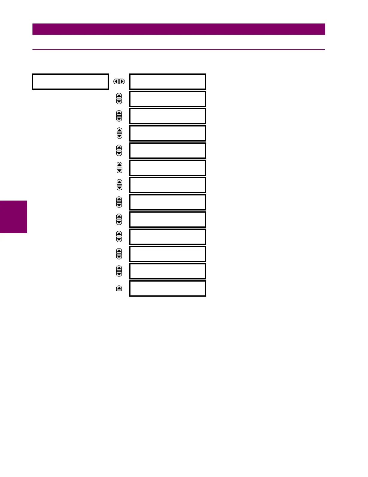
PATH: SETTINGS ÖØ CONTROL ELEMENTS ÖØ PILOT SCHEMES ÖØ POTT SCHEME
This scheme is intended for two-terminal line applications only. It uses an over-reaching zone 2 distance element to essen-
tially compare the direction to a fault at both the ends of the line. Ground directional overcurrent functions available in the
relay can be used in conjunction with the zone 2 distance element to key the scheme and initiate its operation. This pro-
vides increased coverage for high resistance faults.
For proper scheme operation, the zone 2 phase and ground distance elements must be enabled, configured, and set per
the rules of distance relaying. The line pickup element should be enabled, configured and set properly to detect line-end-
open/weak-infeed conditions. If used by this scheme, the selected ground directional overcurrent functions must be
enabled, configured, and set accordingly.
• POTT PERMISSIVE ECHO: If set to "Enabled" this setting will result in sending a permissive echo signal to the remote
end. The permissive signal is echoed back upon receiving a reliable
POTT RX signal from the remote end while the
line-end-open condition is identified by the line pickup logic. The permissive echo is programmed as a one-shot logic.
The echo is sent only once and then the echo logic locks out for a settable period of time (
ECHO LOCKOUT setting). The
duration of the echo pulse does not depend on the duration or shape of the received
POTT RX signal but is settable as
ECHO DURATION.
• POTT RX PICKUP DELAY: This setting enables the relay to cope with spurious receive signals. The delay should be
set longer than the longest spurious TX signal that can occur simultaneously with the zone 2 pickup. The selected
delay will increase the response time of the scheme.
POTT SCHEME
POTT SCHEME
FUNCTION: Disabled
Range: Disabled, Enabled
MESSAGE
POTT PERMISSIVE
ECHO: Disabled
Range: Disabled, Enabled
MESSAGE
POTT RX PICKUP
DELAY: 0.000 s
Range: 0.000 to 65.535 s in steps of 0.001
MESSAGE
TRANS BLOCK PICKUP
DELAY: 0.020 s
Range: 0.000 to 65.535 s in steps of 0.001
MESSAGE
TRANS BLOCK RESET
DELAY: 0.090 s
Range: 0.000 to 65.535 s in steps of 0.001
MESSAGE
ECHO DURATION:
0.100 s
Range: 0.000 to 65.535 s in steps of 0.001
MESSAGE
ECHO LOCKOUT:
0.250 s
Range: 0.000 to 65.535 s in steps of 0.001
MESSAGE
LINE END OPEN PICKUP
DELAY: 0.050 s
Range: 0.000 to 65.535 s in steps of 0.001
MESSAGE
POTT SEAL-IN
DELAY: 0.400 s
Range: 0.000 to 65.535 s in steps of 0.001
MESSAGE
GND DIR O/C FWD:
Off
Range: FlexLogic™ operand
MESSAGE
POTT RX:
Off
Range: FlexLogic™ operand
MESSAGE
POTT SCHEME TARGET:
Self-Reset
Range: Self-Reset, Latched, Disabled
MESSAGE
POTT SCHEME EVENTS:
Disabled
Range: Disabled, Enabled

 Loading...


