5-54 L60 Line Phase Comparison System GE Multilin
5.2 PRODUCT SETUP 5 SETTINGS
5
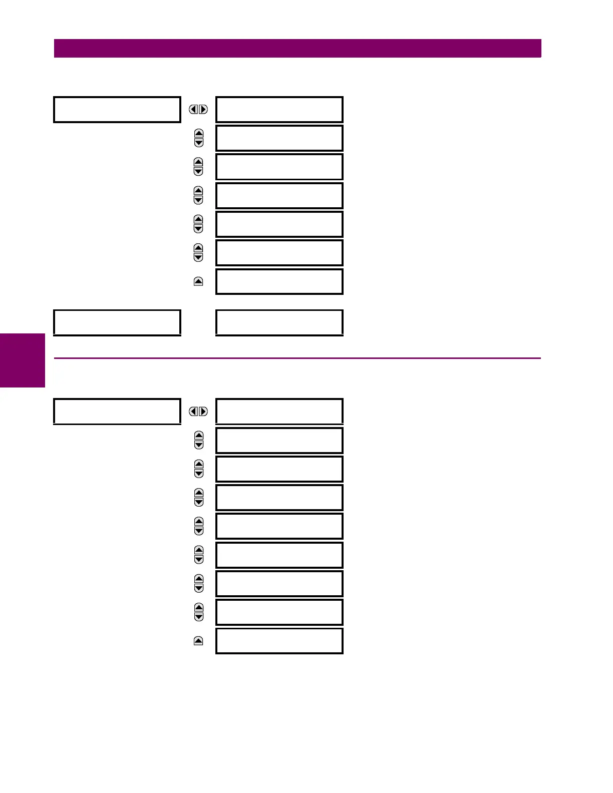
An example user display setup and result is shown below:
5.2.16 DIRECT INPUTS/OUTPUTS
a) MAIN MENU
PATH: SETTINGS Ö PRODUCT SETUP ÖØ DIRECT I/O
Direct inputs and outputs are intended for exchange of status information (inputs and outputs) between UR-series relays
connected directly via type 7 digital communications cards. The mechanism is very similar to IEC 61850 GSSE, except that
communications takes place over a non-switchable isolated network and is optimized for speed. On type 7 cards that sup-
port two channels, direct output messages are sent from both channels simultaneously. This effectively sends direct output
USER DISPLAY 1
DISP 1 TOP LINE:
Current X ~ A
Shows user-defined text with first Tilde marker.
MESSAGE
DISP 1 BOTTOM LINE:
Current Y ~ A
Shows user-defined text with second Tilde marker.
MESSAGE
DISP 1 ITEM 1:
6016
Shows decimal form of user-selected Modbus Register
Address, corresponding to first Tilde marker.
MESSAGE
DISP 1 ITEM 2:
6357
Shows decimal form of user-selected Modbus
Register Address, corresponding to 2nd Tilde marker.
MESSAGE
DISP 1 ITEM 3:
0
This item is not being used - there is no corresponding
Tilde marker in Top or Bottom lines.
MESSAGE
DISP 1 ITEM 4:
0
This item is not being used - there is no corresponding
Tilde marker in Top or Bottom lines.
MESSAGE
DISP 1 ITEM 5:
0
This item is not being used - there is no corresponding
Tilde marker in Top or Bottom lines.
USER DISPLAYS
→
Current X 0.850 A
Current Y 0.327 A
Shows the resultant display content.
DIRECT I/O
DIRECT OUTPUT
DEVICE ID: 1
Range: 1 to 16
MESSAGE
DIRECT I/O CH1 RING
CONFIGURATION: Yes
Range: Yes, No
MESSAGE
DIRECT I/O CH2 RING
CONFIGURATION: Yes
Range: Yes, No
MESSAGE
DIRECT I/O DATA
RATE: 64 kbps
Range: 64 kbps, 128 kbps
MESSAGE
DIRECT I/O CHANNEL
CROSSOVER: Disabled
Range: Disabled, Enabled
MESSAGE
CRC ALARM CH1
See page 5–60.
MESSAGE
CRC ALARM CH2
See page 5–60.
MESSAGE
UNRETURNED
MESSAGES ALARM CH1
See page 5–61.
MESSAGE
UNRETURNED
MESSAGES ALARM CH2
See page 5–61.

 Loading...


