GE Multilin L60 Line Phase Comparison System 5-155
5 SETTINGS 5.5 GROUPED ELEMENTS
5
5.5.8 PHASE CURRENT
a) MAIN MENU
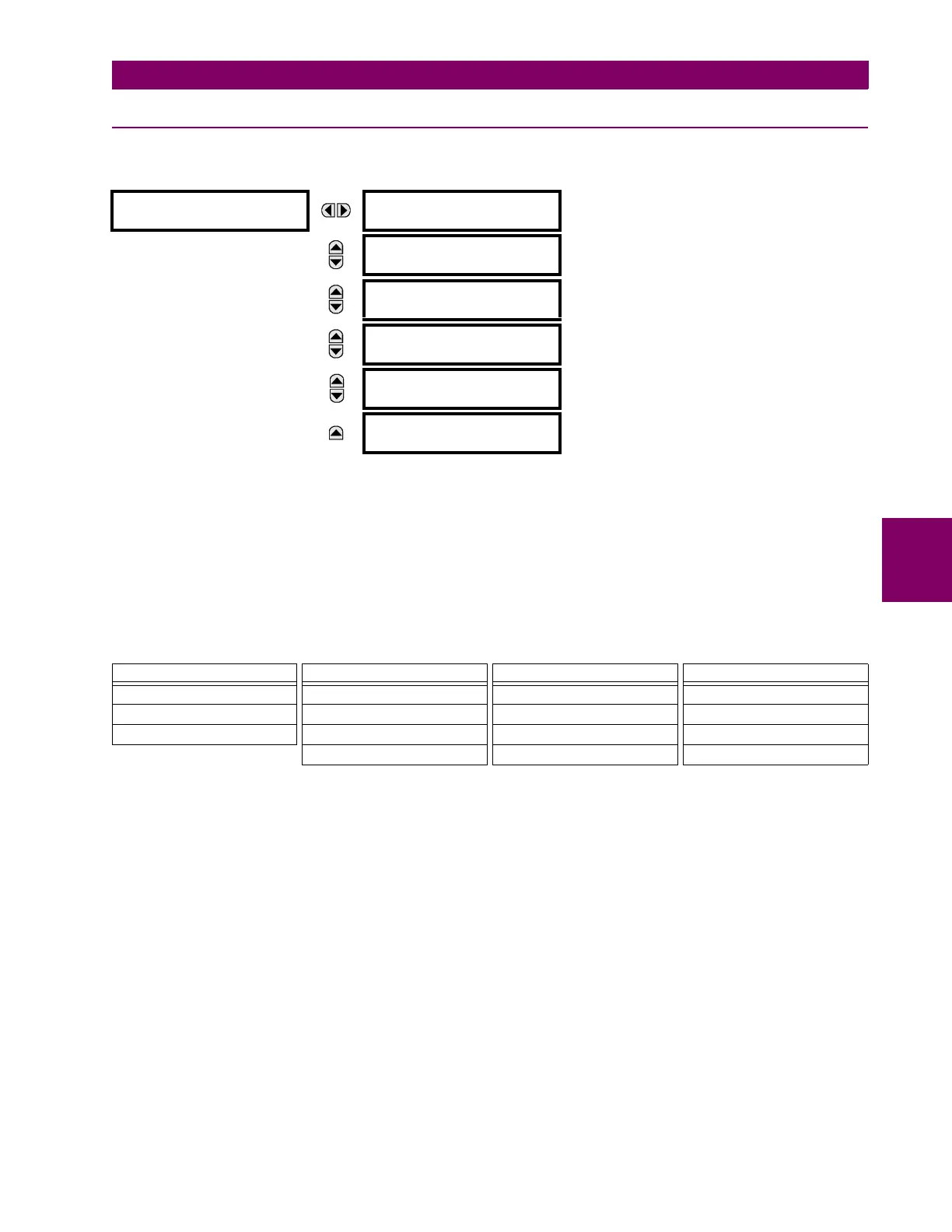
PATH: SETTINGS ÖØ GROUPED ELEMENTS Ö SETTING GROUP 1(6) ÖØ PHASE CURRENT
The L60 Line Phase Comparison System has two (2) Phase Time Overcurrent, two (2) Phase Instantaneous Overcurrent,
and two (2) Phase Directional Overcurrent elements. These are described in the following sub-sections.
b) INVERSE TIME OVERCURRENT CURVE CHARACTERISTICS
The inverse time overcurrent curves used by the time overcurrent elements are the IEEE, IEC, GE Type IAC, and I
2
t stan-
dard curve shapes. This allows for simplified coordination with downstream devices.
If none of these curve shapes is adequate, FlexCurves™ may be used to customize the inverse time curve characteristics.
The definite time curve is also an option that may be appropriate if only simple protection is required.
A time dial multiplier setting allows selection of a multiple of the base curve shape (where the time dial multiplier = 1) with
the curve shape (
CURVE) setting. Unlike the electromechanical time dial equivalent, operate times are directly proportional
to the time multiplier (
TD MULTIPLIER) setting value. For example, all times for a multiplier of 10 are 10 times the multiplier 1
or base curve values. Setting the multiplier to zero results in an instantaneous response to all current levels above pickup.
Time overcurrent time calculations are made with an internal energy capacity memory variable. When this variable indi-
cates that the energy capacity has reached 100%, a time overcurrent element will operate. If less than 100% energy capac-
ity is accumulated in this variable and the current falls below the dropout threshold of 97 to 98% of the pickup value, the
variable must be reduced. Two methods of this resetting operation are available: “Instantaneous” and “Timed”. The “Instan-
taneous” selection is intended for applications with other relays, such as most static relays, which set the energy capacity
directly to zero when the current falls below the reset threshold. The “Timed” selection can be used where the relay must
coordinate with electromechanical relays.
PHASE CURRENT
PHASE TOC1
See page 5–160.
MESSAGE
PHASE TOC2
See page 5–160.
MESSAGE
PHASE IOC1
See page 5–162.
MESSAGE
PHASE IOC2
See page 5–162.
MESSAGE
PHASE
DIRECTIONAL 1
See page 5–163.
MESSAGE
PHASE
DIRECTIONAL 2
See page 5–163.
Table 5–14: OVERCURRENT CURVE TYPES
IEEE IEC GE TYPE IAC OTHER
IEEE Extremely Inverse IEC Curve A (BS142) IAC Extremely Inverse I
2
t
IEEE Very Inverse IEC Curve B (BS142) IAC Very Inverse FlexCurves™ A, B, C, and D
IEEE Moderately Inverse IEC Curve C (BS142) IAC Inverse Recloser Curves
IEC Short Inverse IAC Short Inverse Definite Time

 Loading...


