3-12 L60 Line Phase Comparison System GE Multilin
3.2 WIRING 3 HARDWARE
3
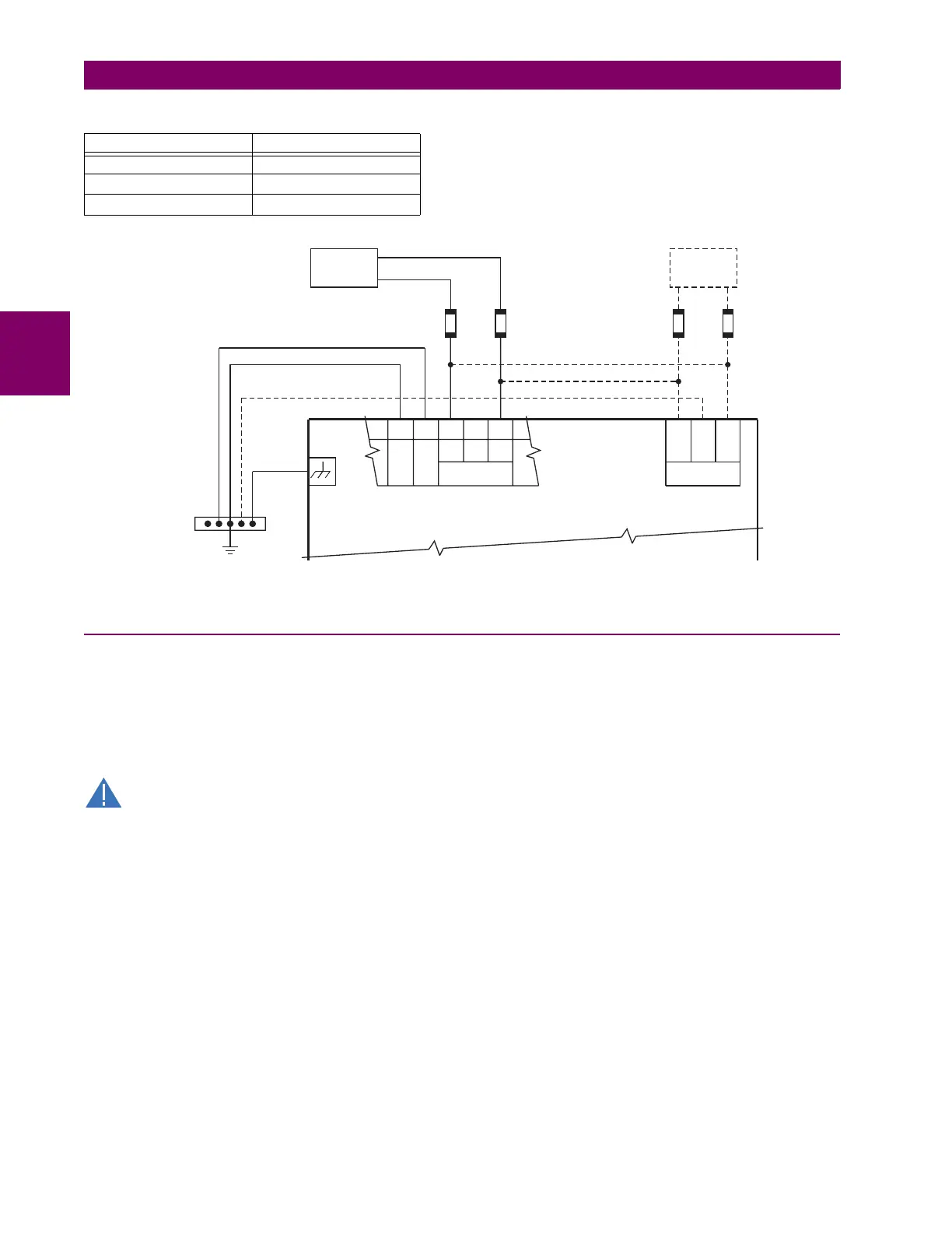
An LED on the front of the control power module shows the status of the power supply:
Figure 3–13: CONTROL POWER CONNECTION
3.2.4 CT AND VT MODULES
A CT/VT module may have voltage inputs on channels 1 through 4 inclusive, or channels 5 through 8 inclusive. Channels 1
and 5 are intended for connection to phase A, and are labeled as such in the relay. Likewise, channels 2 and 6 are intended
for connection to phase B, and channels 3 and 7 are intended for connection to phase C.
Channels 4 and 8 are intended for connection to a single-phase source. For voltage inputs, these channel are labelled as
auxiliary voltage (VX). For current inputs, these channels are intended for connection to a CT between system neutral and
ground, and are labelled as ground current (IG).
Verify that the connection made to the relay nominal current of 1 A or 5 A matches the secondary rating of
the connected CTs. Unmatched CTs may result in equipment damage or inadequate protection.
CT/VT modules may be ordered with a standard ground current input that is the same as the phase current input. Each AC
current input has an isolating transformer and an automatic shorting mechanism that shorts the input when the module is
withdrawn from the chassis. There are no internal ground connections on the current inputs. Current transformers with 1 to
50000 A primaries and 1 A or 5 A secondaries may be used.
The above modules are available with enhanced diagnostics. These modules can automatically detect CT/VT hardware
failure and take the relay out of service.
CT connections for both ABC and ACB phase rotations are identical as shown in the Typical wiring diagram.
The phase voltage channels are used for most metering and protection purposes. The auxiliary voltage channel is used as
input for the synchrocheck and volts-per-hertz features.
The L60 uses a special CT/VT module not available on other UR-series relays. This type 8P module has four current inputs
and special communications inputs/outputs for interfacing with PLCs. The communications interface requires an external
DC source (station battery) to drive inputs/outputs as shown in the L60 channel communications section in this chapter.
LED INDICATION POWER SUPPLY
CONTINUOUS ON OK
ON / OFF CYCLING Failure
OFF Failure
AC or DC
NOTE:
14 gauge stranded
wire with suitable
disconnect devices
is recommended.
Heavy copper conductor
or braided wire
Switchgear
ground bus
UR-series
protection system
FILTER
SURGE
–
+
LOW
+
HIGH
B8b B8a B6a B6b B5b
CONTROL
POWER
827759AA.CDR
—
+
OPTIONAL
ETHERNET SWITCH
AC or DC
GND

 Loading...


