5-64 L60 Line Phase Comparison System GE Multilin
5.3 SYSTEM SETUP 5 SETTINGS
5
5.3SYSTEM SETUP 5.3.1 AC INPUTS
a) CURRENT BANKS
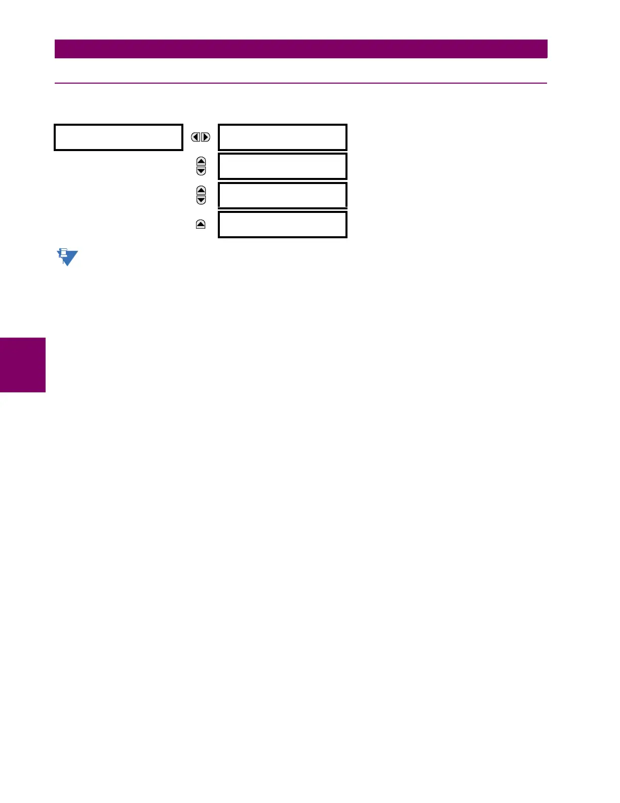
PATH: SETTINGS ÖØ SYSTEM SETUP Ö AC INPUTS Ö CURRENT BANK F1(F5)
Because energy parameters are accumulated, these values should be recorded and then reset immediately
prior to changing CT characteristics.
Two banks of phase and ground CTs can be set, where the current banks are denoted in the following format (X represents
the module slot position letter):
Xa, where X = {F} and a = {1, 5}.
See the Introduction to AC Sources section at the beginning of this chapter for additional details.
These settings are critical for all features that have settings dependent on current measurements. When the relay is
ordered, the CT module must be specified to include a standard or sensitive ground input. As the phase CTs are connected
in wye (star), the calculated phasor sum of the three phase currents (IA + IB + IC = neutral current = 3Io) is used as the
input for the neutral overcurrent elements. In addition, a zero-sequence (core balance) CT which senses current in all of the
circuit primary conductors, or a CT in a neutral grounding conductor may also be used. For this configuration, the ground
CT primary rating must be entered. To detect low level ground fault currents, the sensitive ground input may be used. In this
case, the sensitive ground CT primary rating must be entered. Refer to chapter 3 for more details on CT connections.
Enter the rated CT primary current values. For both 1000:5 and 1000:1 CTs, the entry would be 1000. For correct opera-
tion, the CT secondary rating must match the setting (which must also correspond to the specific CT connections used).
The following example illustrates how multiple CT inputs (current banks) are summed as one source current. Given If the
following current banks:
• F1: CT bank with 500:1 ratio.
• F5: CT bank with 1000: ratio.
The following rule applies:
(EQ 5.6)
1 pu is the highest primary current. In this case, 1000 is entered and the secondary current from the 500:1 and 800:1 ratio
CTs will be adjusted to that created by a 1000:1 CT before summation. If a protection element is set up to act on SRC 1 cur-
rents, then a pickup level of 1 pu will operate on 1000 A primary.
The same rule applies for current sums from CTs with different secondary taps (5 A and 1 A).
CURRENT BANK F1
PHASE CT F1
PRIMARY: 1 A
Range: 1 to 65000 A in steps of 1
MESSAGE
PHASE CT F1
SECONDARY: 1 A
Range: 1 A, 5 A
MESSAGE
GROUND CT F1
PRIMARY: 1 A
Range: 1 to 65000 A in steps of 1
MESSAGE
GROUND CT F1
SECONDARY: 1 A
Range: 1 A, 5 A

 Loading...


