5-264 L60 Line Phase Comparison System GE Multilin
5.7 INPUTS/OUTPUTS 5 SETTINGS
5
DIRECT OUT 2 OPERAND: "HYB POTT TX1"
DIRECT OUT 3 OPERAND: "DIRECT INPUT 5" (forward a message from 1 to 3)
DIRECT OUT 4 OPERAND: "DIRECT INPUT 6" (forward a message from 3 to 1)
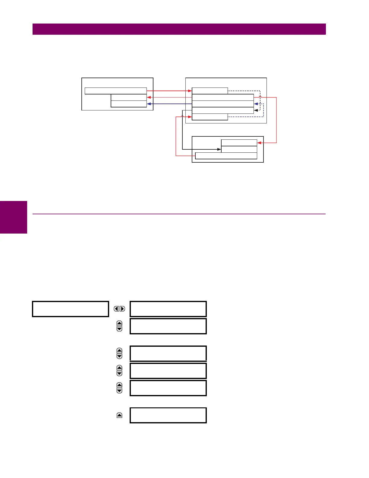
Signal flow between the three IEDs is shown in the figure below:
Figure 5–142: SIGNAL FLOW FOR DIRECT INPUT AND OUTPUT – EXAMPLE 3
In three-terminal applications, both the remote terminals must grant permission to trip. Therefore, at each terminal, direct
inputs 5 and 6 should be ANDed in FlexLogic™ and the resulting operand configured as the permission to trip (HYB POTT
RX1 setting).
5.7.11 TELEPROTECTION INPUTS AND OUTPUTS
a) OVERVIEW
The relay provides sixteen teleprotection inputs on communications channel 1 (numbered 1-1 through 1-16) and sixteen
teleprotection inputs on communications channel 2 (on two-terminals two-channel and three-terminal systems only, num-
bered 2-1 through 2-16). The remote relay connected to channels 1 and 2 of the local relay is programmed by assigning
FlexLogic™ operands to be sent via the selected communications channel. This allows the user to create distributed pro-
tection and control schemes via dedicated communications channels. Some examples are directional comparison pilot
schemes and direct transfer tripping. It should be noted that failures of communications channels will affect teleprotection
functionality. The teleprotection function must be enabled to utilize the inputs.
b) TELEPROTECTION INPUTS
PATH: SETTINGS ÖØ INPUTS/OUTPUTS ÖØ TELEPROTECTION Ö TELEPROT INPUTS
TELEPROT INPUTS
TELEPROT INPUT 1-1
DEFAULT: Off
Range: Off, On, Latest/Off, Latest/On
MESSAGE
TELEPROT INPUT 1-2
DEFAULT: Off
Range: Off, On, Latest/Off, Latest/On
↓
MESSAGE
TELEPROT INPUT 1-16
DEFAULT: Off
Range: Off, On, Latest/Off, Latest/On
MESSAGE
TELEPROT INPUT 2-1
DEFAULT: Off
Range: Off, On, Latest/Off, Latest/On
MESSAGE
TELEPROT INPUT 2-2
DEFAULT: Off
Range: Off, On, Latest/Off, Latest/On
↓
MESSAGE
TELEPROT INPUT 2-16
DEFAULT: Off
Range: Off, On, Latest/Off, Latest/On
842717A1.CDR
UR IED 3
UR IED 2UR IED 1
DIRECT OUT 2 = HYB POTT TX1
DIRECT INPUT 5
DIRECT INPUT 6
DIRECT OUT 2 = HYB POTT TX1
DIRECT INPUT 5
DIRECT INPUT 6
DIRECT OUT 2 = HYB POTT TX1
DIRECT INPUT 6
DIRECT OUT 4 = DIRECT INPUT 6
DIRECT OUT 3 = DIRECT INPUT 5
DIRECT INPUT 5

 Loading...


