2-4 L60 Line Phase Comparison System GE Multilin
2.1 INTRODUCTION 2 PRODUCT DESCRIPTION
2
2.1.2 ORDERING
The L60 is available as a 19-inch rack horizontal mount unit or a reduced size (¾) vertical mount unit, and consists of the
following modules: CPU, faceplate, power supply, CPU, CTs and VTs, digital input and outputs, transducer inputs and out-
puts, and inter-relay communications. Each of these modules can be supplied in a number of configurations specified at the
time of ordering. The information required to completely specify the relay is provided in the following tables (see chapter 3
for additional details of relay modules).
The L60 is specified with two CT/VT modules (8F and 8P). When the L60 is applied in two-breaker configurations (such as
breaker-and-a-half or ring configurations), the currents from the two CTs are summed internally within the relay or exter-
nally. If the voltage is not supplies to the relay, some functions (such as distance, undervoltage, and synchrocheck) will not
be available.
Order codes are subject to change without notice. Refer to the GE Multilin ordering page at
http://www.GEindustrial.com/multilin/order.htm
for the latest details concerning L60 ordering options.
The order codes for the horizontal mount units are shown below.
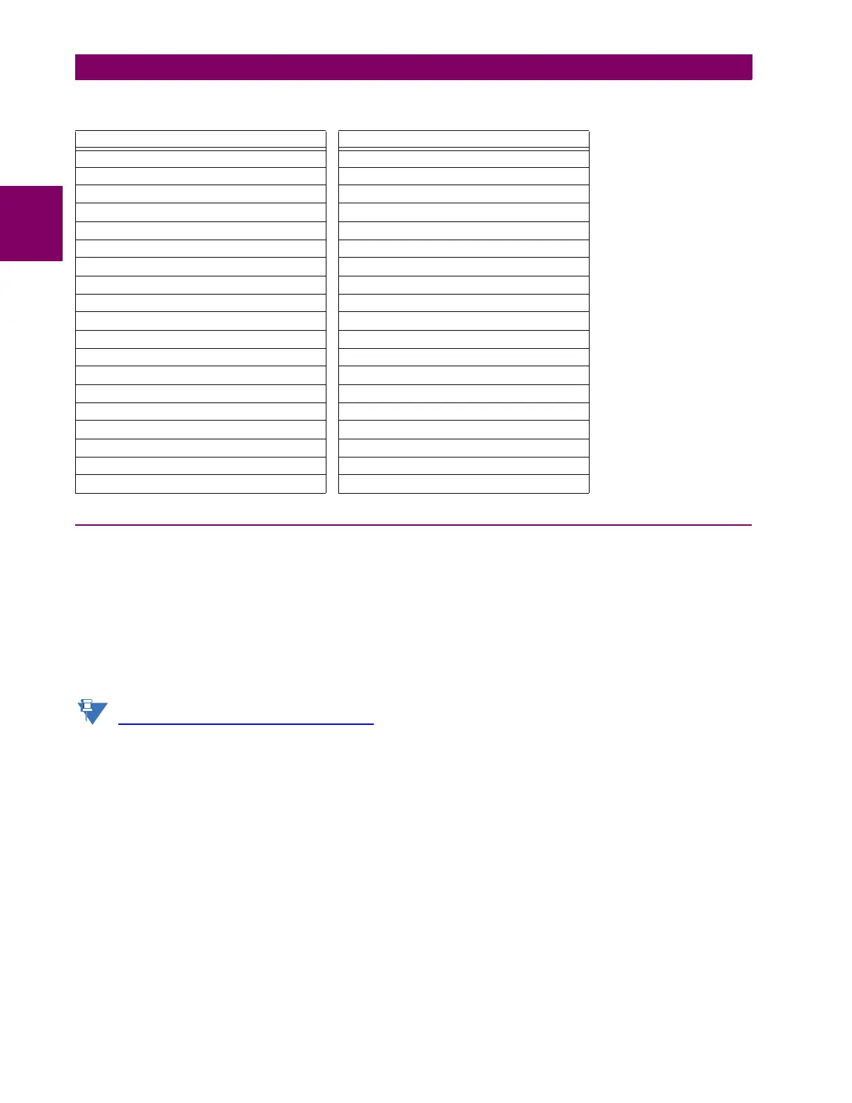
Table 2–2: OTHER DEVICE FUNCTIONS
FUNCTION FUNCTION
Breaker Arcing Current (I
2
t) IEC 61850 Communications (optional)
Breaker Control Modbus Communications
Contact Inputs (up to 96) Modbus User Map
Contact Outputs (up to 64) Non-Volatile Latches
Control Pushbuttons Non-Volatile Selector Switch
CT Failure Detector Open Breaker Echo
Data Logger Oscillography
Digital Counters (8) Pilot Scheme (POTT)
Digital Elements (48) Setting Groups (6)
Disconnect Switches Time Synchronization over SNTP
DNP 3.0 or IEC 60870-5-104 Communications Transducer Inputs/Outputs
Event Recorder Trip Bus
Fault Location User Definable Display
Fault Reporting User Programmable LEDs
FlexElements™ (8) User Programmable Pushbuttons
FlexLogic™ Equations User Programmable Self-Tests
Line Pickup Virtual Inputs (64)
Load Encroachment Virtual Outputs (96)
Metering: Current, Voltage, Power, Frequency VT Fuse Failure

 Loading...


