GE Multilin L60 Line Phase Comparison System 5-219
5 SETTINGS 5.6 CONTROL ELEMENTS
5
5.6.7 DIGITAL ELEMENTS
PATH: SETTINGS ÖØ CONTROL ELEMENTS ÖØ DIGITAL ELEMENTS Ö DIGITAL ELEMENT 1(48)
There are 48 identical digital elements available, numbered 1 to 48. A digital element can monitor any FlexLogic™ operand
and present a target message and/or enable events recording depending on the output operand state. The digital element
settings include a name which will be referenced in any target message, a blocking input from any selected FlexLogic™
operand, and a timer for pickup and reset delays for the output operand.
• DIGITAL ELEMENT 1 INPUT: Selects a FlexLogic™ operand to be monitored by the digital element.
• DIGITAL ELEMENT 1 PICKUP DELAY: Sets the time delay to pickup. If a pickup delay is not required, set to "0".
• DIGITAL ELEMENT 1 RESET DELAY: Sets the time delay to reset. If a reset delay is not required, set to “0”.
• DIGITAL ELEMENT 1 PICKUP LED: This setting enables or disabled the digital element pickup LED. When set to
“Disabled”, the operation of the pickup LED is blocked.
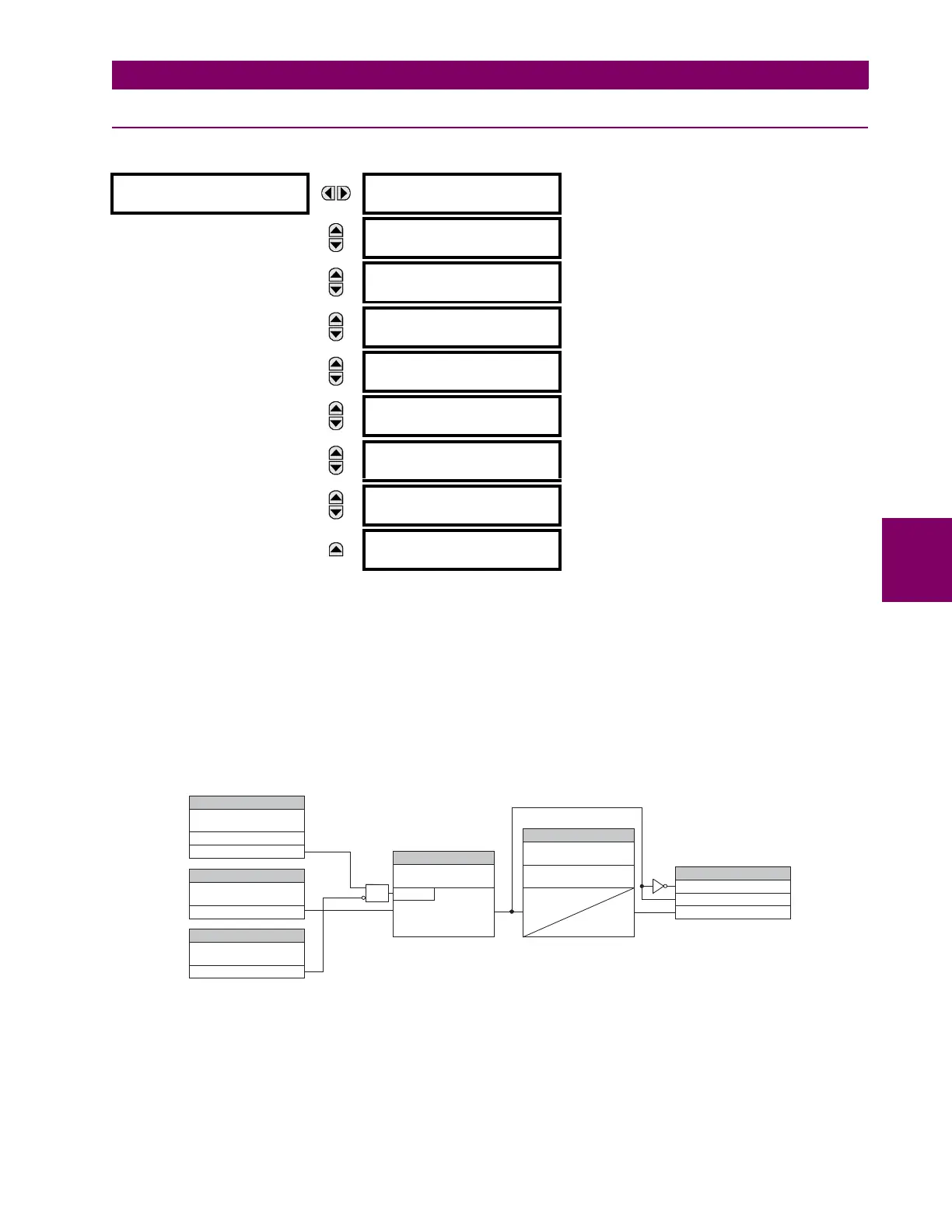
Figure 5–121: DIGITAL ELEMENT SCHEME LOGIC
CIRCUIT MONITORING APPLICATIONS:
Some versions of the digital input modules include an active voltage monitor circuit connected across form-A contacts. The
voltage monitor circuit limits the trickle current through the output circuit (see technical specifications for form-A).
DIGITAL ELEMENT 1
DIGITAL ELEMENT 1
FUNCTION: Disabled
Range: Disabled, Enabled
MESSAGE
DIG ELEM 1 NAME:
Dig Element 1
Range: 16 alphanumeric characters
MESSAGE
DIG ELEM 1 INPUT:
Off
Range: FlexLogic™ operand
MESSAGE
DIG ELEM 1 PICKUP
DELAY: 0.000 s
Range: 0.000 to 999999.999 s in steps of 0.001
MESSAGE
DIG ELEM 1 RESET
DELAY: 0.000 s
Range: 0.000 to 999999.999 s in steps of 0.001
MESSAGE
DIG ELEMENT 1
PICKUP LED: Enabled
Range: Disabled, Enabled
MESSAGE
DIG ELEM 1 BLOCK:
Off
Range: FlexLogic™ operand
MESSAGE
DIGITAL ELEMENT 1
TARGET: Self-reset
Range: Self-reset, Latched, Disabled
MESSAGE
DIGITAL ELEMENT 1
EVENTS: Disabled
Range: Disabled, Enabled
SETTING
DIGITAL ELEMENT 01
FUNCTION:
Disabled = 0
Enabled = 1
DIGITAL ELEMENT 01
BLOCK:
Off=0
FLEXLOGIC OPERANDS
DIG ELEM 01 DPO
DIG ELEM 01 PKP
SETTING
827042A1.VSD
DIGITAL ELEMENT 01
INPUT:
Off=0
SETTING
INPUT = 1
RUN
t
PKP
t
RST
DIGITAL ELEMENT 01
PICKUP DELAY:
SETTINGS
DIGITAL ELEMENT 01
RESET DELAY:
AND
SETTING
DIGITAL ELEMENT 01
NAME:
DIG ELEM 01 OP

 Loading...


