GE Multilin L60 Line Phase Comparison System 5-201
5 SETTINGS 5.6 CONTROL ELEMENTS
5
5.6CONTROL ELEMENTS 5.6.1 OVERVIEW
Control elements are generally used for control rather than protection. See the Introduction to Elements section at the
beginning of this chapter for further information.
5.6.2 TRIP BUS
PATH: SETTINGS ÖØ CONTROL ELEMENTS ÖØ TRIP BUS ÖØ TRIP BUS 1(6)
The trip bus element allows aggregating outputs of protection and control elements without using FlexLogic™ and assign-
ing them a simple and effective manner. Each trip bus can be assigned for either trip or alarm actions. Simple trip condition-
ing such as latch, delay, and seal-in delay are available.
The easiest way to assign element outputs to a trip bus is through the EnerVista UR Setup software A protection summary
is displayed by navigating to a specific protection or control protection element and checking the desired bus box. Once the
desired element is selected for a specific bus, a list of element operate-type operands are displayed and can be assigned
to a trip bus. If more than one operate-type operand is required, it may be assigned directly from the trip bus menu.
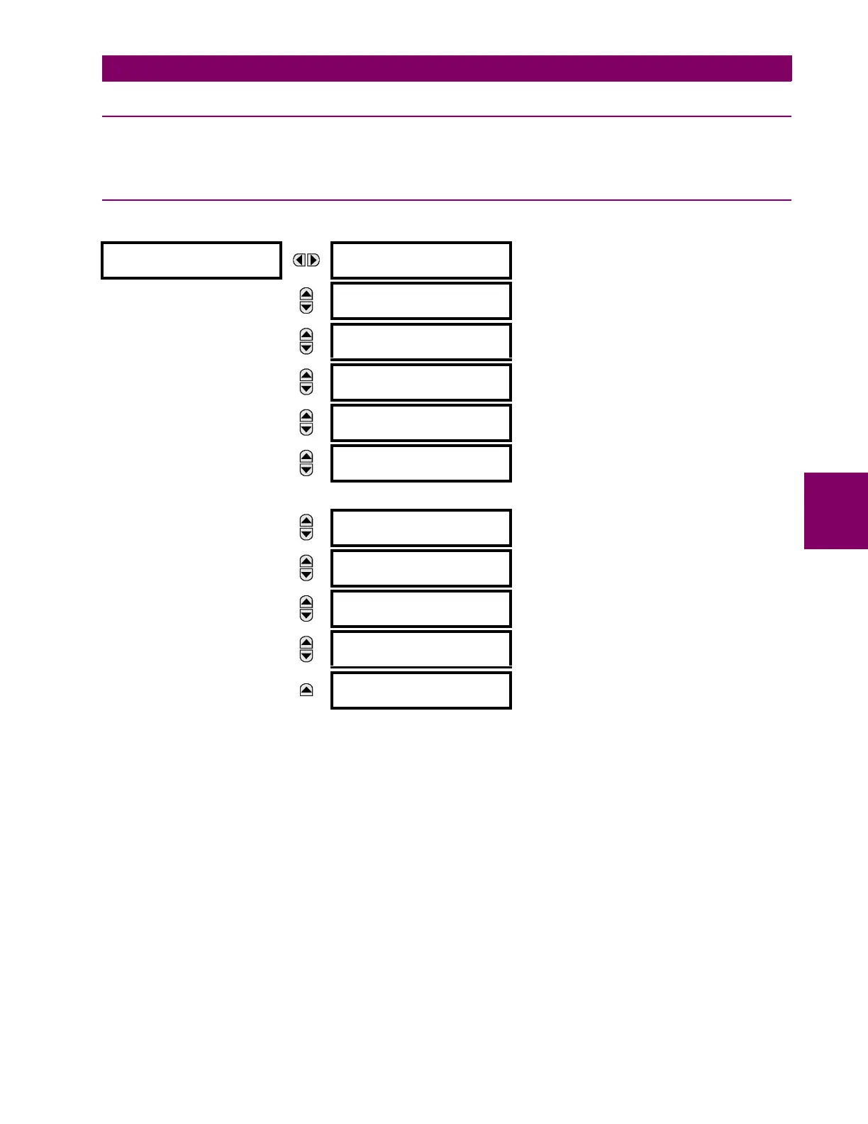
TRIP BUS 1
TRIP BUS 1
FUNCTION: Disabled
Range: Enabled, Disabled
MESSAGE
TRIP BUS 1 BLOCK:
Off
Range: FlexLogic™ operand
MESSAGE
TRIP BUS 1 PICKUP
DELAY: 0.00 s
Range: 0.00 to 600.00 s in steps of 0.01
MESSAGE
TRIP BUS 1 RESET
DELAY: 0.00 s
Range: 0.00 to 600.00 s in steps of 0.01
MESSAGE
TRIP BUS 1 INPUT 1:
Off
Range: FlexLogic™ operand
MESSAGE
TRIP BUS 1 INPUT 2:
Off
Range: FlexLogic™ operand
↓
MESSAGE
TRIP BUS 1 INPUT 16:
Off
Range: FlexLogic™ operand
MESSAGE
TRIP BUS 1
LATCHING: Disabled
Range: Enabled, Disabled
MESSAGE
TRIP BUS 1 RESET:
Off
Range: FlexLogic™ operand
MESSAGE
TRIP BUS 1 TARGET:
Self-reset
Range: Self-reset, Latched, Disabled
MESSAGE
TRIP BUS 1
EVENTS: Disabled
Range: Enabled, Disabled

 Loading...


