2-16 L60 Line Phase Comparison System GE Multilin
2.2 SPECIFICATIONS 2 PRODUCT DESCRIPTION
2
2.2.6 POWER SUPPLY
LOW RANGE
Nominal DC voltage: 24 to 48 V
Min/max DC voltage: 20 / 60 V
Voltage loss hold-up: 20 ms duration at nominal
NOTE: Low range is DC only.
HIGH RANGE
Nominal DC voltage: 125 to 250 V
Min/max DC voltage: 88 / 300 V
Nominal AC voltage: 100 to 240 V at 50/60 Hz
Min/max AC voltage: 88 / 265 V at 25 to 100 Hz
Voltage loss hold-up: 200 ms duration at nominal
ALL RANGES
Volt withstand: 2 × Highest Nominal Voltage for 10 ms
Power consumption: typical = 15 to 20 W/VA
maximum = 50 W/VA
contact factory for exact order code con-
sumption
INTERNAL FUSE
RATINGS
Low range power supply: 8 A / 250 V
High range power supply: 4 A / 250 V
INTERRUPTING CAPACITY
AC: 100 000 A RMS symmetrical
DC: 10 000 A
2.2.7 OUTPUTS
FORM-A RELAY
Make and carry for 0.2 s: 30 A as per ANSI C37.90
Carry continuous: 6 A
Break (DC inductive, L/R = 40 ms):
Operate time: < 4 ms
Contact material: silver alloy
LATCHING RELAY
Make and carry for 0.2 s: 30 A as per ANSI C37.90
Carry continuous: 6 A
Break at L/R of 40 ms: 0.25 A DC max.
Operate time: < 4 ms
Contact material: silver alloy
Control: separate operate and reset inputs
Control mode: operate-dominant or reset-dominant
FORM-A VOLTAGE MONITOR
Applicable voltage: approx. 15 to 250 V DC
Trickle current: approx. 1 to 2.5 mA
FORM-A CURRENT MONITOR
Threshold current: approx. 80 to 100 mA
FORM-C AND CRITICAL FAILURE RELAY
Make and carry for 0.2 s: 30 A as per ANSI C37.90
Carry continuous: 8 A
Break (DC inductive, L/R = 40 ms):
Operate time: < 8 ms
Contact material: silver alloy
FAST FORM-C RELAY
Make and carry: 0.1 A max. (resistive load)
Minimum load impedance:
Operate time: < 0.6 ms
Internal Limiting Resistor: 100 Ω, 2 W
SOLID-STATE OUTPUT RELAY
Operate and release time: <100 μs
Maximum voltage: 265 V DC
Maximum continuous current: 5 A at 45°C; 4 A at 65°C
Make and carry:
for 0.2 s: 30 A as per ANSI C37.90
for 0.03 s 300 A
Breaking capacity:
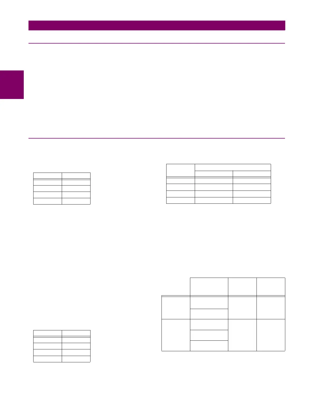
VOLTAGE CURRENT
24 V 1 A
48 V 0.5 A
125 V 0.3 A
250 V 0.2 A
VOLTAGE CURRENT
24 V 1 A
48 V 0.5 A
125 V 0.3 A
250 V 0.2 A
INPUT
VOLTAGE
IMPEDANCE
2 W RESISTOR 1 W RESISTOR
250 V DC 20 KΩ 50 KΩ
120 V DC 5 KΩ 2 KΩ
48 V DC 2 KΩ 2 KΩ
24 V DC 2 KΩ 2 KΩ
Note: values for 24 V and 48 V are the same due to a
required 95% voltage drop across the load impedance.
UL508 Utility
application
(autoreclose
scheme)
Industrial
application
Operations/
interval
5000 ops /
1 s-On, 9 s-Off
5ops/
0.2 s-On,
0.2 s-Off
within 1
minute
10000 ops /
0.2 s-On,
30 s-Off
1000 ops /
0.5 s-On, 0.5 s-Off
Break
capability
(0 to 250 V
DC)
3.2 A
L/R = 10 ms
10 A
L/R = 40 ms
10 A
L/R = 40 ms
1.6 A
L/R = 20 ms
0.8 A
L/R = 40 ms
 Loading...


