5-260 L60 Line Phase Comparison System GE Multilin
5.7 INPUTS/OUTPUTS 5 SETTINGS
5
Remote outputs (1 to 32) are FlexLogic™ operands inserted into GSSE/GOOSE messages that are transmitted to remote
devices on a LAN. Each digital point in the message must be programmed to carry the state of a specific FlexLogic™ oper-
and. The above operand setting represents a specific DNA function (as shown in the following table) to be transmitted.
b) USERST BIT PAIRS
PATH: SETTINGS ÖØ INPUTS/OUTPUTS ÖØ REMOTE OUTPUTS UserSt BIT PAIRS Ö REMOTE OUTPUTS UserSt- 1(32) BIT PAIR
Remote outputs 1 to 32 originate as GSSE/GOOSE messages to be transmitted to remote devices. Each digital point in the
message must be programmed to carry the state of a specific FlexLogic™ operand. The setting above is used to select the
operand which represents a specific UserSt function (as selected by the user) to be transmitted.
The following setting represents the time between sending GSSE/GOOSE messages when there has been no change of
state of any selected digital point. This setting is located in the PRODUCT SETUP ÖØ COMMUNICATIONS ÖØ IEC 61850 PROTO-
COL ÖØ GSSE/GOOSE CONFIGURATION settings menu.
For more information on GSSE/GOOSE messaging, refer to Remote Inputs/Outputs Overview in the
Remote Devices section.
5.7.9 RESETTING
PATH: SETTINGS ÖØ INPUTS/OUTPUTS ÖØ RESETTING
Some events can be programmed to latch the faceplate LED event indicators and the target message on the display. Once
set, the latching mechanism will hold all of the latched indicators or messages in the set state after the initiating condition
has cleared until a RESET command is received to return these latches (not including FlexLogic™ latches) to the reset
state. The RESET command can be sent from the faceplate Reset button, a remote device via a communications channel,
or any programmed operand.
When the RESET command is received by the relay, two FlexLogic™ operands are created. These operands, which are
stored as events, reset the latches if the initiating condition has cleared. The three sources of RESET commands each cre-
ate the
RESET OP FlexLogic™ operand. Each individual source of a RESET command also creates its individual operand
RESET OP (PUSHBUTTON), RESET OP (COMMS) or RESET OP (OPERAND) to identify the source of the command. The setting
shown above selects the operand that will create the
RESET OP (OPERAND) operand.
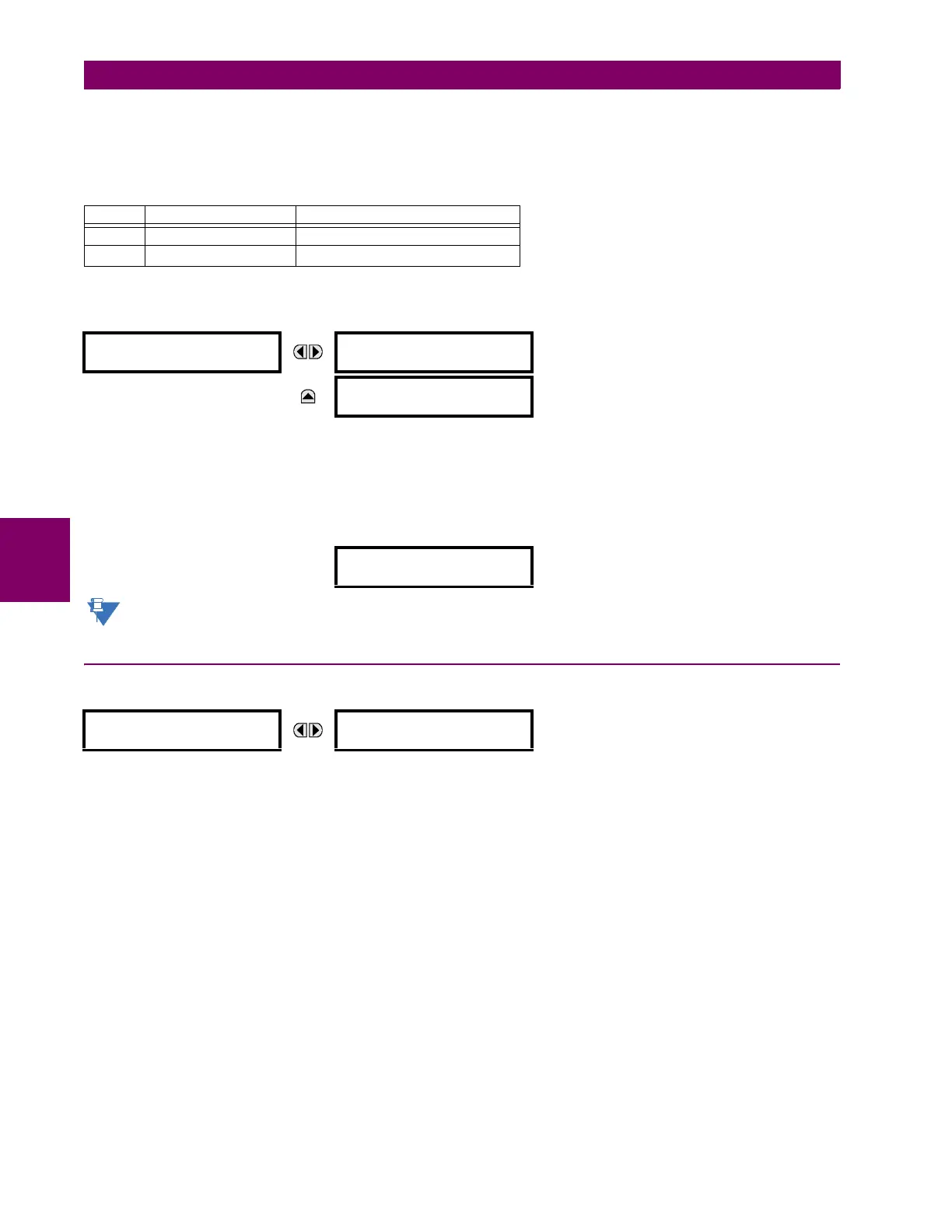
Table 5–25: IEC 61850 DNA ASSIGNMENTS
DNA IEC 61850 DEFINITION FLEXLOGIC™ OPERAND
1 Test IEC 61850 TEST MODE
2 ConfRev IEC 61850 CONF REV
REMOTE OUTPUTS
UserSt- 1 BIT PAIR
UserSt- 1 OPERAND:
Off
Range: FlexLogic™ operand
MESSAGE
UserSt- 1 EVENTS:
Disabled
Range: Disabled, Enabled
DEFAULT GSSE/GOOSE
UPDATE TIME: 60 s
Range: 1 to 60 s in steps of 1
RESETTING
RESET OPERAND:
Off
Range: FlexLogic™ operand

 Loading...


