GE Multilin L60 Line Phase Comparison System 2-19
2 PRODUCT DESCRIPTION 2.2 SPECIFICATIONS
2
The power budgets for the 1300nm ELED are cal-
culated from the manufacturer's transmitter
power and receiver sensitivity at ambient temper-
ature. At extreme temperatures these values will
deviate based on component tolerance. On aver-
age, the output power will decrease as the tem-
perature is increased by a factor 1dB / 5°C.
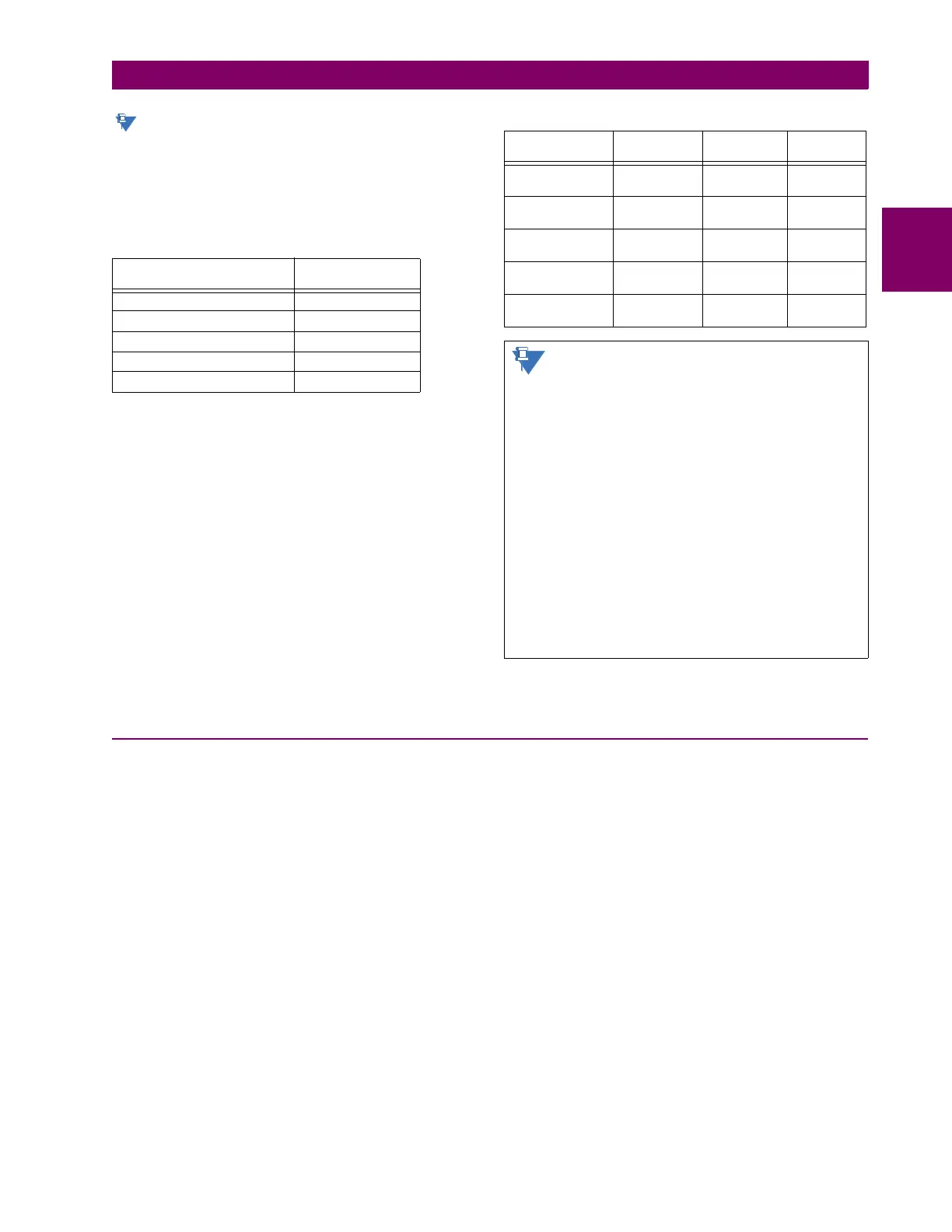
MAXIMUM OPTICAL INPUT POWER
TYPICAL LINK DISTANCE
Compensated difference in transmitting and receiving (channel
asymmetry) channel delays using GPS satellite clock: 10 ms
2.2.10 ENVIRONMENTAL
AMBIENT TEMPERATURES
Storage temperature: –40 to 85°C
Operating temperature: –40 to 60°C; the LCD contrast may be
impaired at temperatures less than –
20°C
HUMIDITY
Humidity: operating up to 95% (non-condensing) at
55°C (as per IEC60068-2-30 variant 1,
6days).
OTHER
Altitude: 2000 m (maximum)
Pollution degree: II
Overvoltage category: II
Ingress protection: IP40 front, IP20 back
EMITTER, FIBER TYPE MAX. OPTICAL
INPUT POWER
820 nm LED, Multimode –7.6 dBm
1300 nm LED, Multimode –11 dBm
1300 nm ELED, Singlemode –14 dBm
1300 nm Laser, Singlemode –14 dBm
1550 nm Laser, Singlemode –14 dBm
EMITTER TYPE CABLE
TYPE
CONNECTOR
TYPE
TYPICAL
DISTANCE
820 nm LED,
multimode
62.5/125 μmST 1.65 km
1300 nm LED,
multimode
62.5/125 μm ST 3.8 km
1300 nm ELED,
single mode
9/125 μm ST 11.4 km
1300 nm Laser,
single mode
9/125 μm ST 64 km
1550 nm Laser,
single-mode
9/125 μm ST 105 km
Typical distances listed are based on the fol-
lowing assumptions for system loss. As
actual losses will vary from one installation to
another, the distance covered by your system
may vary.
CONNECTOR LOSSES (TOTAL OF BOTH ENDS)
ST connector 2 dB
FIBER LOSSES
820 nm multimode 3 dB/km
1300 nm multimode 1 dB/km
1300 nm singlemode 0.35 dB/km
1550 nm singlemode 0.25 dB/km
Splice losses: One splice every 2 km,
at 0.05 dB loss per splice.
SYSTEM MARGIN
3 dB additional loss added to calculations to compensate for
all other losses.
 Loading...


