5-276 L60 Line Phase Comparison System GE Multilin
5.9 TESTING 5 SETTINGS
5
5.9.3 FORCE CONTACT OUTPUTS
PATH: SETTINGS ÖØ TESTING ÖØ FORCE CONTACT OUTPUTS
The relay contact outputs can be pre-programmed to respond to the test mode.
If set to “Disabled”, the contact output remains fully operational. If operates when its control operand is logic 1 and will
resets when its control operand is logic 0. If set to “Energized”, the output will close and remain closed for the entire dura-
tion of the test mode, regardless of the status of the operand configured to control the output contact. If set to “De-ener-
gized”, the output will open and remain opened for the entire duration of the test mode regardless of the status of the
operand configured to control the output contact. If set to “Freeze”, the output retains its position from before entering the
test mode, regardless of the status of the operand configured to control the output contact.
These settings are applied two ways. First, external circuits may be tested by energizing or de-energizing contacts. Sec-
ond, by controlling the output contact state, relay logic may be tested and undesirable effects on external circuits avoided.
Example 1: Initiating test mode through user-programmable pushbutton 1
For example, the test mode can be initiated from user-programmable pushbutton 1. The pushbutton will be programmed as
“Latched” (pushbutton pressed to initiate the test, and pressed again to terminate the test). During the test, digital input 1
should remain operational, digital inputs 2 and 3 should open, and digital input 4 should close. Also, contact output 1 should
freeze, contact output 2 should open, contact output 3 should close, and contact output 4 should remain fully operational.
The required settings are shown below.
To enable user-programmable pushbutton 1 to initiate the test mode, make the following changes in the
SETTINGS ÖØ
TESTING Ö TEST MODE menu: TEST MODE FUNCTION: “Enabled” and TEST MODE INITIATE: “PUSHBUTTON 1 ON”
Make the following changes to configure the contact inputs and outputs. In the SETTINGS ÖØ TESTING ÖØ FORCE CONTACT
INPUTS and FORCE CONTACT OUTPUTS menus, set:
FORCE Cont Ip 1: “Disabled”, FORCE Cont Ip 2: “Open”, FORCE Cont Ip 3: “Open”, and FORCE Cont Ip 4: “Closed”
FORCE Cont Op 1: “Freeze”, FORCE Cont Op 2: “De-energized”, FORCE Cont Op 3: “Energized”,
and
FORCE Cont Op 4: “Disabled”
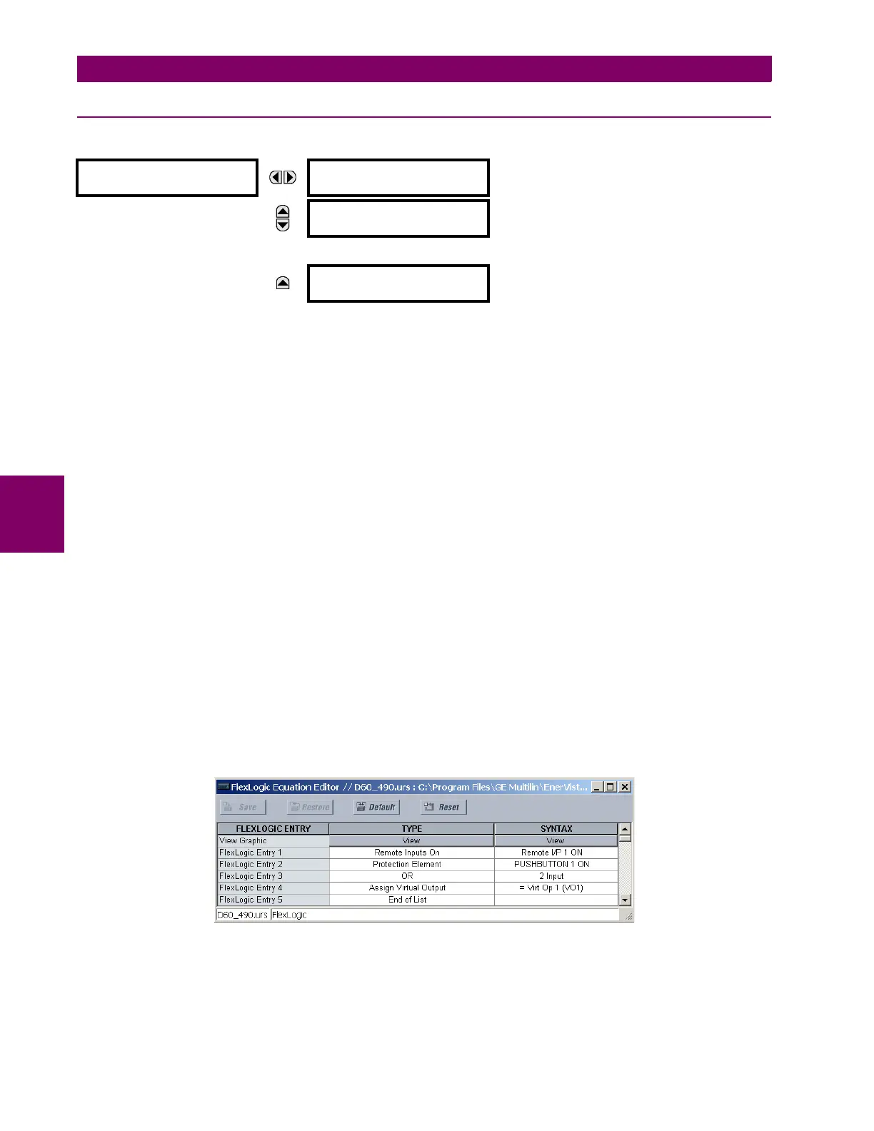
Example 2: Initiating a test from user-programmable pushbutton 1 or through remote input 1
In this example, the test can be initiated locally from user-programmable pushbutton 1 or remotely through remote input 1.
Both the pushbutton and the remote input will be programmed as “Latched”. Write the following FlexLogic™ equation:
Set the user-programmable pushbutton as latching by changing
SETTINGS Ö PRODUCT SETUP ÖØ USER-PROGRAMMABLE
PUSHBUTTONS
Ö USER PUSHBUTTON 1 Ö PUSHBUTTON 1 FUNCTION to “Latched”. To enable either pushbutton 1 or remote
input 1 to initiate the Test mode, make the following changes in the
SETTINGS ÖØ TESTING Ö TEST MODE menu:
TEST MODE FUNCTION: “Enabled” and TEST MODE INITIATE: “VO1”
FORCE CONTACT
OUTPUTS
FORCE Cont Op 1
:Disabled
Range: Disabled, Energized, De-energized, Freeze
MESSAGE
FORCE Cont Op 2
:Disabled
Range: Disabled, Energized, De-energized, Freeze
↓
MESSAGE
FORCE Cont Op xx
:Disabled
Range: Disabled, Energized, De-energized, Freeze