5-256 L60 Line Phase Comparison System GE Multilin
5.7 INPUTS/OUTPUTS 5 SETTINGS
5
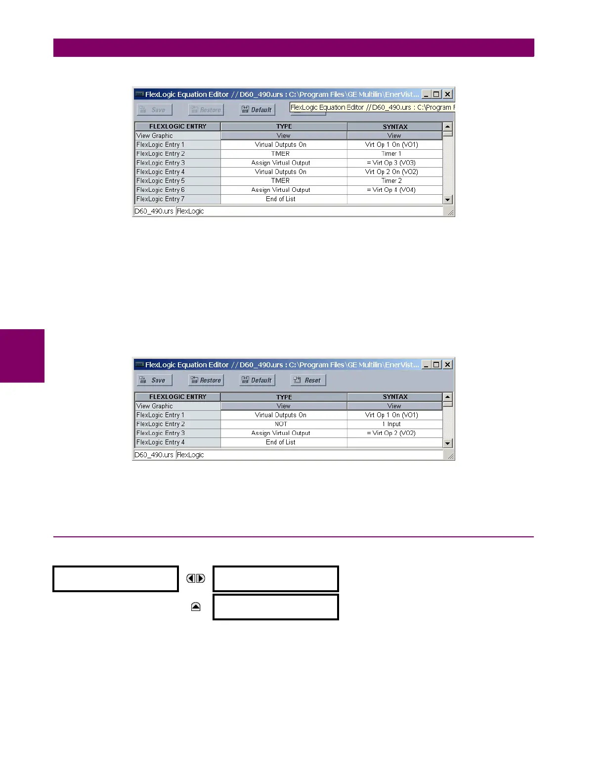
Write the following FlexLogic™ equation (EnerVista UR Setup example shown):
Both timers (Timer 1 and Timer 2) should be set to 20 ms pickup and 0 ms dropout.
Program the Latching Outputs by making the following changes in the
SETTINGS ÖØ INPUTS/OUTPUTS ÖØ CONTACT OUT-
PUTS
Ö CONTACT OUTPUT H1a and CONTACT OUTPUT H1c menus (assuming an H4L module):
OUTPUT H1a OPERATE: “VO1” OUTPUT H1c OPERATE: “VO2”
OUTPUT H1a RESET: “VO4” OUTPUT H1c RESET: “VO3”
Application Example 4:
A latching contact H1a is to be controlled from a single virtual output VO1. The contact should stay closed as long as VO1
is high, and should stay opened when VO1 is low. Program the relay as follows.
Write the following FlexLogic™ equation (EnerVista UR Setup example shown):
Program the Latching Outputs by making the following changes in the SETTINGS ÖØ INPUTS/OUTPUTS ÖØ CONTACT OUT-
PUTS Ö CONTACT OUTPUT H1a menu (assuming an H4L module):
OUTPUT H1a OPERATE: “VO1”
OUTPUT H1a RESET: “VO2”
5.7.4 VIRTUAL OUTPUTS
PATH: SETTINGS ÖØ INPUTS/OUTPUTS ÖØ VIRTUAL OUTPUTS Ö VIRTUAL OUTPUT 1(96)
There are 96 virtual outputs that may be assigned via FlexLogic™. If not assigned, the output will be forced to ‘OFF’ (Logic
0). An ID may be assigned to each virtual output. Virtual outputs are resolved in each pass through the evaluation of the
FlexLogic™ equations. Any change of state of a virtual output can be logged as an event if programmed to do so.
For example, if Virtual Output 1 is the trip signal from FlexLogic™ and the trip relay is used to signal events, the settings
would be programmed as follows:
VIRTUAL OUTPUT 1
VIRTUAL OUTPUT 1 ID
Virt Op 1
Range: Up to 12 alphanumeric characters
MESSAGE
VIRTUAL OUTPUT 1
EVENTS: Disabled
Range: Disabled, Enabled

 Loading...


