GE RAFT VOLUSON™ P8/VOLUSON™P6
DIRECTION 5775469, R
EVISION 3 DRAFT (JULY 19, 2018) BASIC SERVICE MANUAL
3-66 Section 3-8 - System Configuration
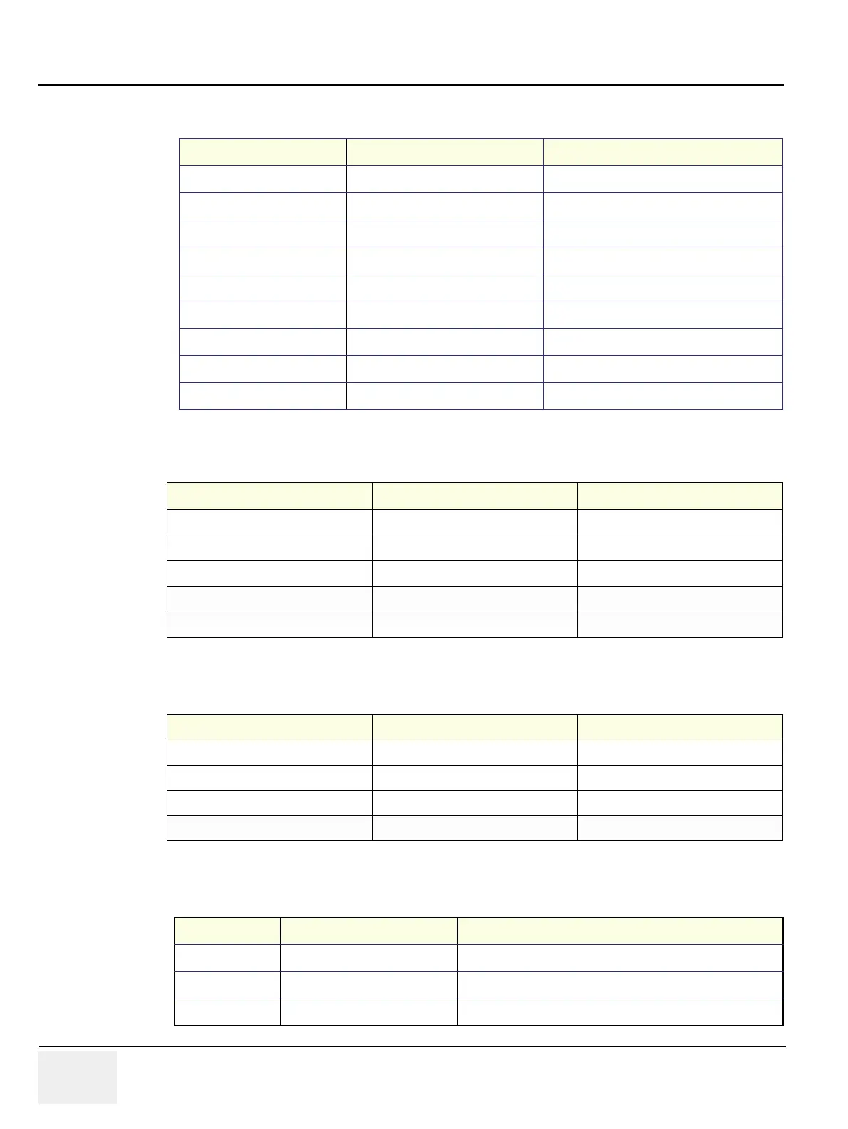
Table 3-4 RGB Out Connector, 19 Pin
Pin No Output Signal Description
1 Red RGB Output
2 Greed RGB Output
3 Blue RGB Output
13 Horizontal - sync Horizontal -sync
14 Vertical -sync Vertical -sync
12 DDC_DATA DATA
15 DDC_CLK CLK
5,6,7,8.10 GND Ground
4,9,11 NC No Connection
Table 3-5 Network Connector, RJ45 Modular 8 Pin
Pin No Output Signal Description
1 ETHER TD Ethernet RD+
2 ETHER TD Ethernet RD-
3 ETHER RD Ethernet TD+
6 ETHER RD Ethernet TD-
Others NC No connection
Table 3-6 USB 2.0 Connectors
Pin No Output Signal Description
1 VCC USB Power Supply
2 - Data USB Data (-)
3 + Data USB Data (+)
4 GND USB Power Ground
Table 3-7 Audio Connectors
Pin No Output Signal Description
1GND GND
2 Audio_Left Audio_Left
3 Audio_Right Audio_Right

 Loading...


