GE DRAFT VOLUSON™ P8/VOLUSON™P6
DIRECTION 5775469, R
EVISION 3 DRAFT (JULY 19, 2018) BASIC SERVICE MANUAL
Chapter 3 - Setup Instructions 3-65
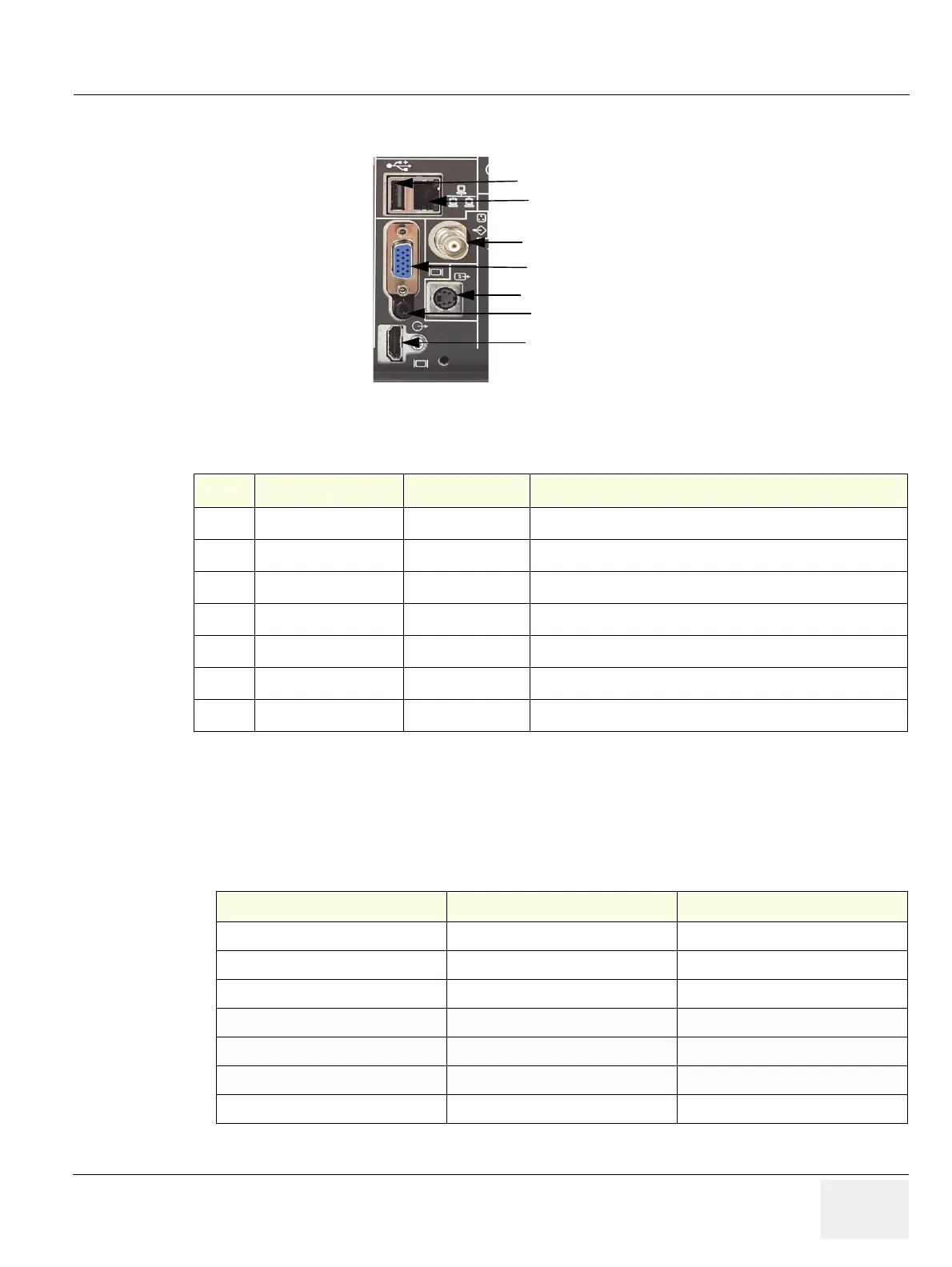
3-8-3 External I/O Connectors
3-8-3-1 External I/O Pin Outs
Figure 3-61 External I/O Connectors - on Rear of System
Table 3-2 External I/O Connector - Description
Item Connector Name Table Number Description
1 HDMI Out
Table 3-3 HDMI Connector for external Monitor
2NETWORK
Table 3-5 DICOM input/output, twisted pair RJ-45 10/100 megabit/s
3USB
Table 3-6 USB-2.0 port
4 RGB Out
Table 3-4 RGB Connector for external Monitor
5 Audio Out
Table 3-7 Audio out for external speaker
6 COMPOSITE (Option)
N/A COMPOSITE Output
7 S-VIDEO (Option)
N/A S-VIDEO Output
Table 3-3 HDMI out Connector, 23 Pin
Pin No Output Signal Description
1 ~ 12 TMDS clock/data/Shield TMDS clock/data/Shield
13 CEC Not used
14 N/C Reserved
14, 15 SCL/SDA I2C Line
17,20,21,22,23 GND Ground
18 5V Power
19 Hot plug Not used

 Loading...


