4 - Sprayer Setup
70
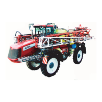
Installation of Control Unit Brackets
Find a suitable place in the tractor cabin to fit the control units.
Best recommended position is to the right of the driver seat.
The supplied tractor pillar bracket (A) has a hole spacing of 100 and 120
mm, which fits most tractors. Threaded holes for fitting may be hidden
behind the front corner cover. Check the tractor’s instruction book for
information regarding attachment points.
Supplied are three tubes (B) for fitting. One, two or all three may be used.
They can be bent and shortened. A spacer (C) is also supplied to allow
further attachment possibilities. Find the best solution for your tractor or
vehicle.
The tube (B) plate is staggered so that, if correctly orientated, all boxes
will line up.
μ
ATTENTION! See also the controllers instruction book for further
details of fitting the controller equipment.
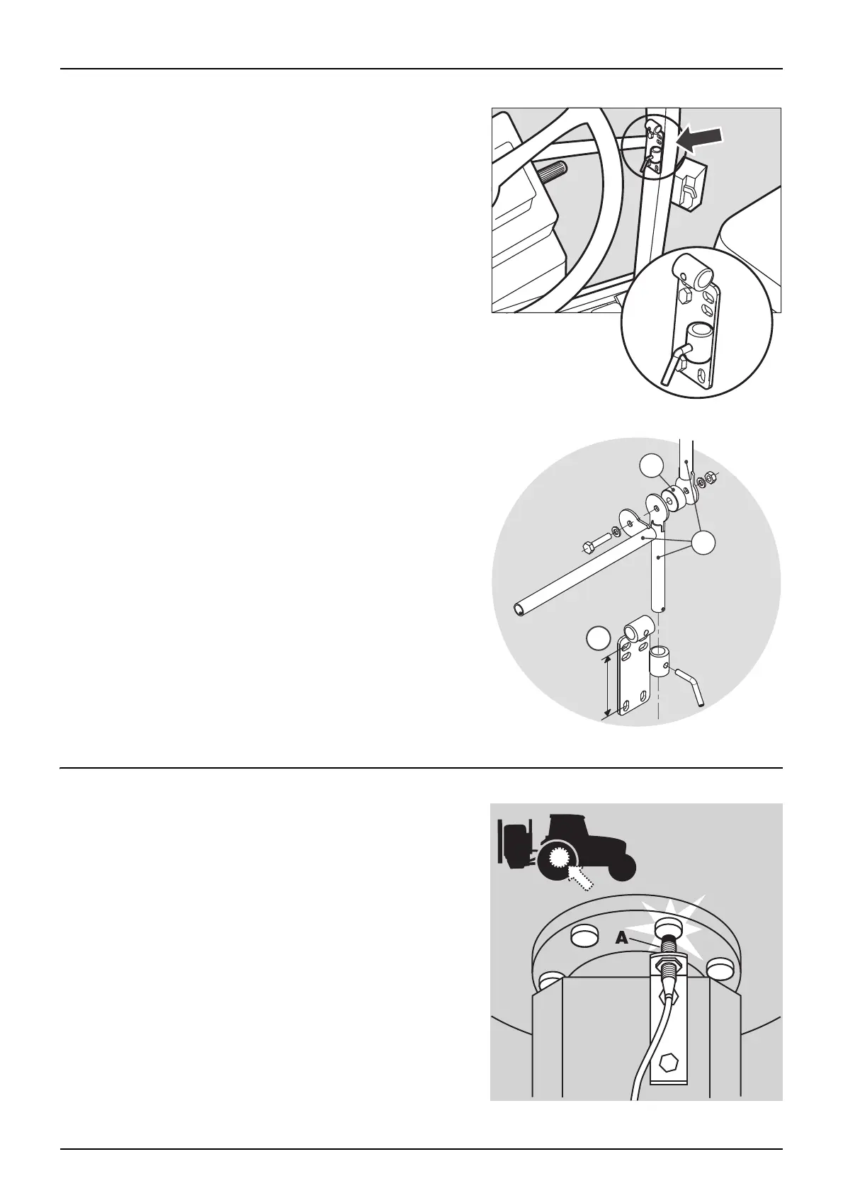
Speed Transducer for Tractors
Note the following if the speed transducer is fitted to the tractor.
The speed transducer (A) and the speed ring should be located at the
inside of the tractor’s right wheel.
The sensor is an inductive type that requires a metallic protrusion (e.g. a
bolt head) passing by in order to trigger a signal. It should be adjusted,
so that the transducer is placed to the centre of the holes in the speed
ring (vertical direction).
• Recommended distance between speed ring and transducer (A) is
4 mm ± 2. Check this in the entire circumference of the ring when
spinning the wheel by hand.
Correct fitting is indicated by a constant flashing of the transducer, when
the wheel is rotating.
 Loading...