www.modelflight.com.au – World’s best source of JR products
ustment
The screen contrast adjustment feature of the XP8
10
3 allows the
user to select the proper tint of the screen for improved clarity
and visibility in all weather conditions and temperatures.
T
o
increase the contrast (darken the screen), simply turn the
power switch ON and press the SEL and DA
T
A
+ keys
simultaneously
. T
o
decrease the contrast (lighten the screen),
press the SEL and DA
T
A
- keys simultaneously
.
uirements
It is extremely impor
tant that your radio system be correctly
installed in your model. Here are a few suggestions on the
installation of your JR equipment.
1.
W
rap the receiver in protective foam rubber that is no les
than 3/8 inch thick. Secure the foam to the receiver with #6
rubber bands. This protects the receiver in the event of a cras
or a ver
y hard landing.
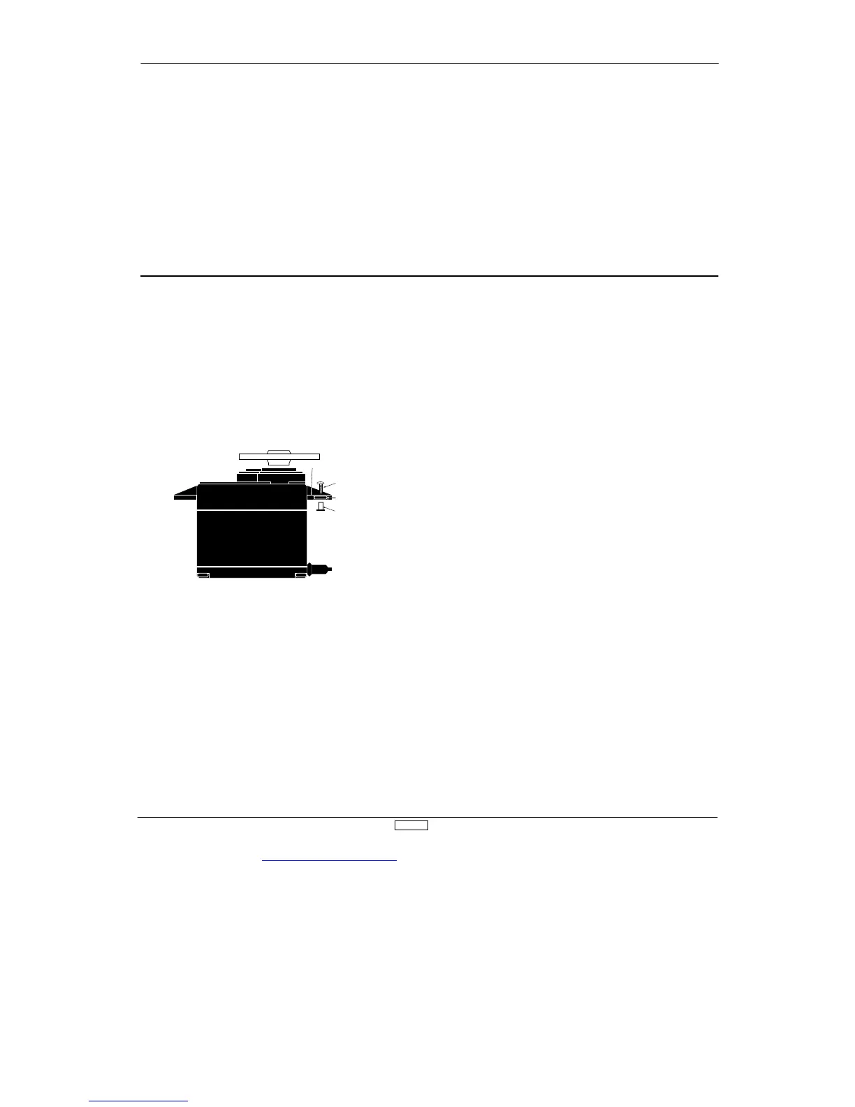
Servo Mounting Tab
Screw
Rubber Grommet
Brass Bushing
2.
The ser
vos should be mounted using rubber grommets and
brass bushings to isolate them from vibration. Do not over-tighten
the mounting screws — this will negate the vibration absorption
ef
fect of the rubber grommets. The diagram at left will assist you
in properly mounting your ser
vo.
The brass bushings are pushed from the bottom up in the rubber
grommets. When the ser
vo screw is tightened securely
, it
provides the proper security
, as well as the proper vibration
isolation, for your ser
vo.
3.
The ser
vos must be able to move freely over their entire
range of travel. Make sure that the control linkages do not bind
or impede the movement of any of the ser
vos.
4.
Mount all switches away from the engine exhaust and awa
from any high vibration areas. Make sure each switch operates
freely and is able to operate over its full travel.
5.
Mount the receiver antenna fir
mly to the airplane to ensure
that it will not become entangled in the propeller or control
sur
faces.

 Loading...