www.modelflight.com.au – World’s best source of JR products
4
ccessing the Programable Mixing Functions
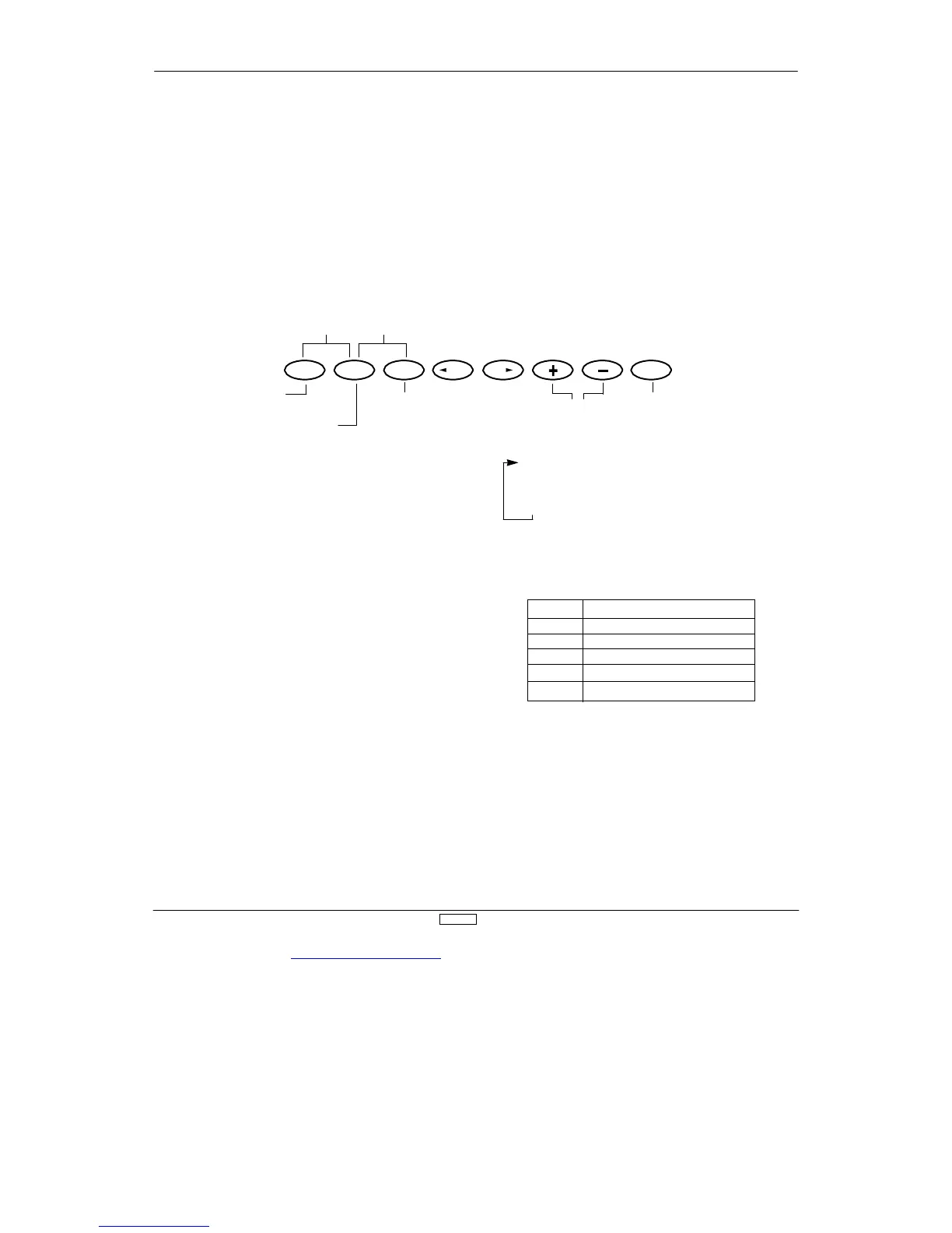
Place the transmitter power switch in the ON position. Press the
Mode UP and DN ke
to enter the Function
Mode. Press either the UP or DN keys until PROG. Mix 1
appears in the upper left por
tion of the LCD (refer to figur
below).
Press the UP and DN keys
simultaneously to enter/exit
the Function Mode
Press the DN and Select key
simultaneously to access th
rammable
UP
DN
SELECT CH CH CLEAR
Mixin
ustment function
Press to move
the curso
Press either the + or - key to
activate the mixing function; to
increase/decrease values; and
to change the EXP function
from OFF to ON
Press the reset value at
cursor to factory preset
postion/value or to
inhibit Mixin
function
Mixing Channel
↓
Point
↓
Switch
The XP8
10
3 of
fers six (6) programmable mixes to be used for a
number of dif
ferent purposes. The functions allows mixing any
one channel to any other channel.
The mix can remain ON at all times, or be switched OFF in
flight using a number of dif
ferent switches. (Refer to figure 4
.1
3B).
Each channel is identified by a four character name (i.e.,
ileron - AILE, Elevator - ELEV
, etc.). The channel appearing first
is known as the “master channel,” or the channel to which you
want to mix. The second channel is known as the “slave
channel,” or the channel that is being mixed into the master
channel. For example, AILE - RUDD would indicate aileron to
rudder mixing — each time the aileron stick is moved, the
aileron will deflect, and the rudder will automatically move in the
direction and to the value input. Mixing is propor
tional, so
small inputs of the master channel will produce small outputs of
the slave channel. Each programmable mix has a mixing
“of
fset.” The purpose of the mixing of
fset is to redefine the
neutral position of the slave channel.
(4.13B)
SW Indicate
Switch Lever Position When Mixing Is On
ON
Mixing Always On
MIX
Mixing Switch T
oward Self
LAND
Flap Switch In land Position
ELE>F
Flap Switch In ELEV Position
GEAR
Retracting Landing Gear SW T
oward Self
Multi-Point Programmable Mixing
Programmable mixes 1 and 2 have the capability for multi-poin
programmable mixing. The graphic mixing curve, located on th
right side of your screen, indicates the mixing cur
ve selected
and is a useful reference tool when adjusting or storing points.
Up to 5 points can be stored, and these points can be moved
independently to any desired ser
vo position from 0 to 100%.

 Loading...