Model 6517B Electrometer Reference Manual Section 5: Measurement options
6517B-901-01 Rev. C / August 2015 5-11
Electrometer input circuitry
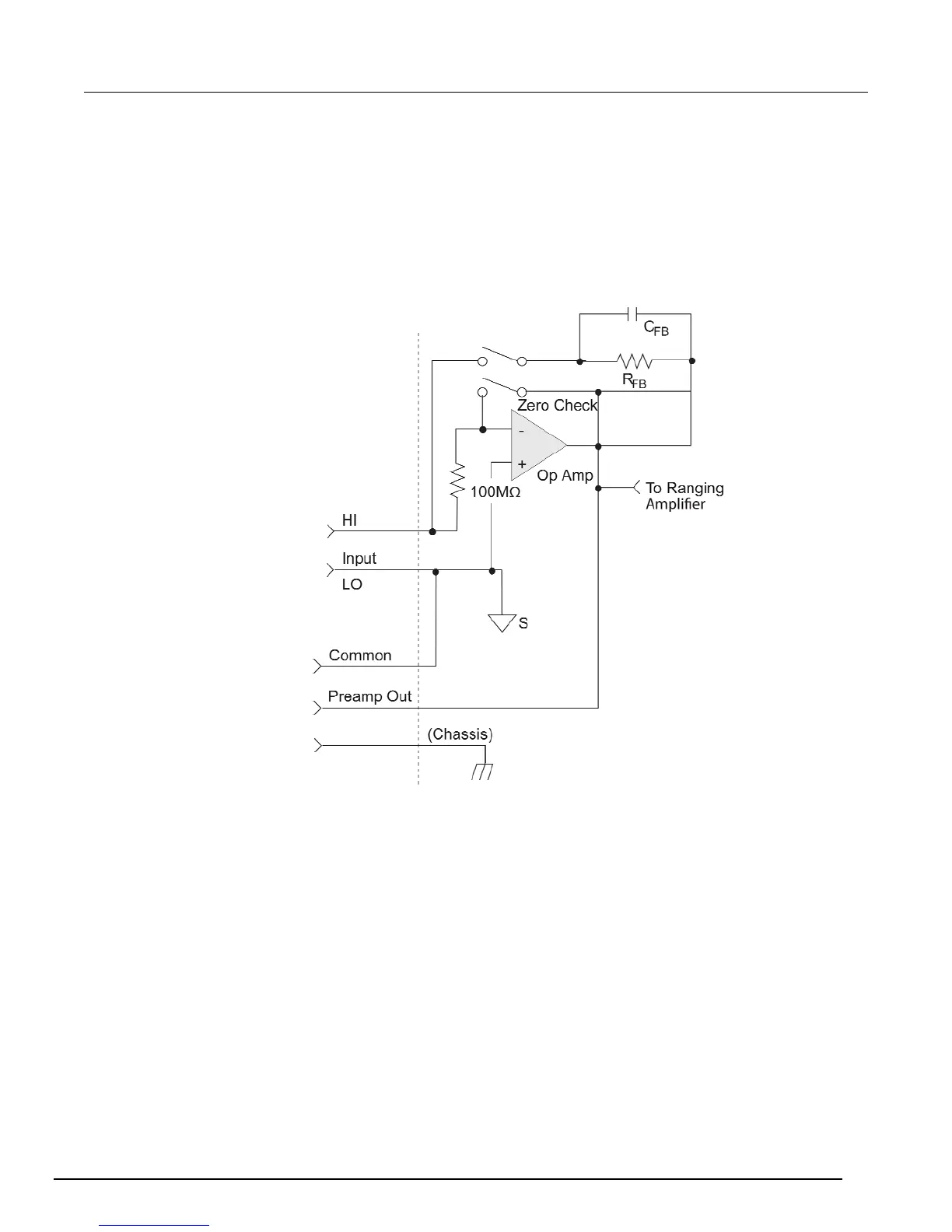
A simplified diagram of the electrometer input in the external feedback mode is shown in the following
figure. An input current applied to the inverting (-) input of the operational amplifier (op amp) is nulled
by a current feedback through the internal feedback network made up of R
FB
and C
FB
. Because the
output of the op amp appears at the PREAMP OUT, this internal network can be replaced by an
external network connected between the preamp output and Input HI connections.
Figure 61: Electrometer input circuitry (external feedback mode)

 Loading...


