Section 6: Test sequences Model 6517B Electrometer Reference Manual
6-2 6517B-901-01 Rev. C / August 2015
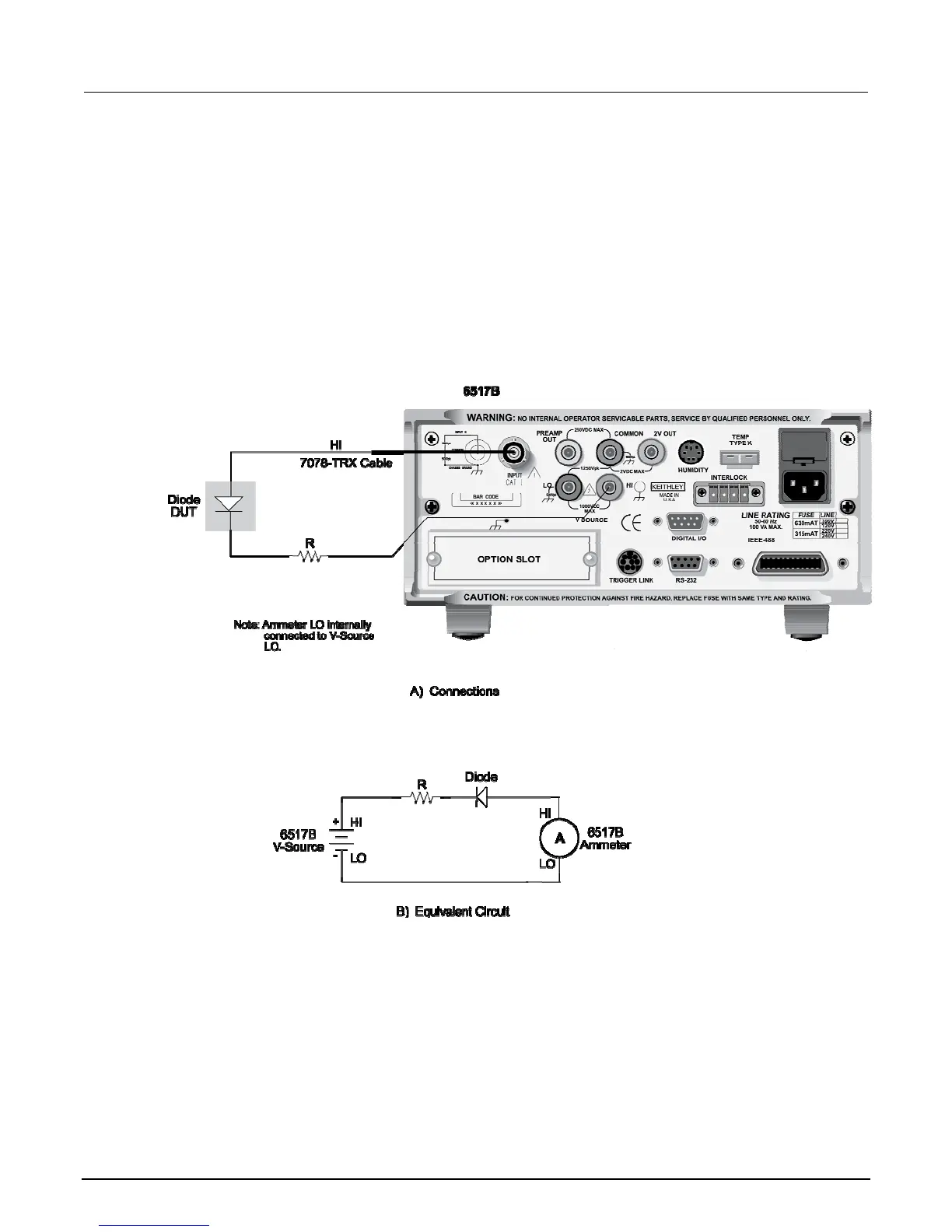
Diode leakage current test
This test is used to measure the leakage current for a diode. The following figure shows the
connections and the simplified schematic. By sourcing a positive voltage, the leakage current through
the diode is measured. Note that if you source a negative voltage, you forward bias the diode.
Resistor R is used to limit current in the event that the diode shorts out or it becomes forward biased.
Select a value of R limits current to 20 mA or less.
This test allows you to measure the current at various voltage levels. When the test is configured, you
specify the start voltage (START V), the step voltage (STEP V), the stop voltage (STOP V) and the
DELAY between steps.
Figure 67: Diode leakage current test connections
The following figure shows an example using the default test parameters. When the test is run, 10
current measurements is performed (one at each voltage step) and stored in the buffer. This test is
selected and configured from the CONFIGURE SEQUENCE menu (DEV-CHAR; DIODE). This test
allows you to measure the current at various voltage levels. When the test is configured, you specify
the start voltage (START V), the step voltage (STEP V), the stop voltage (STOP V) and the DELAY
between steps.

 Loading...


