Model 6517B Electrometer Reference Manual Section 10: Limits, digital I/O, and scanning
6517B-901-01 Rev. C / August 2015 10-7
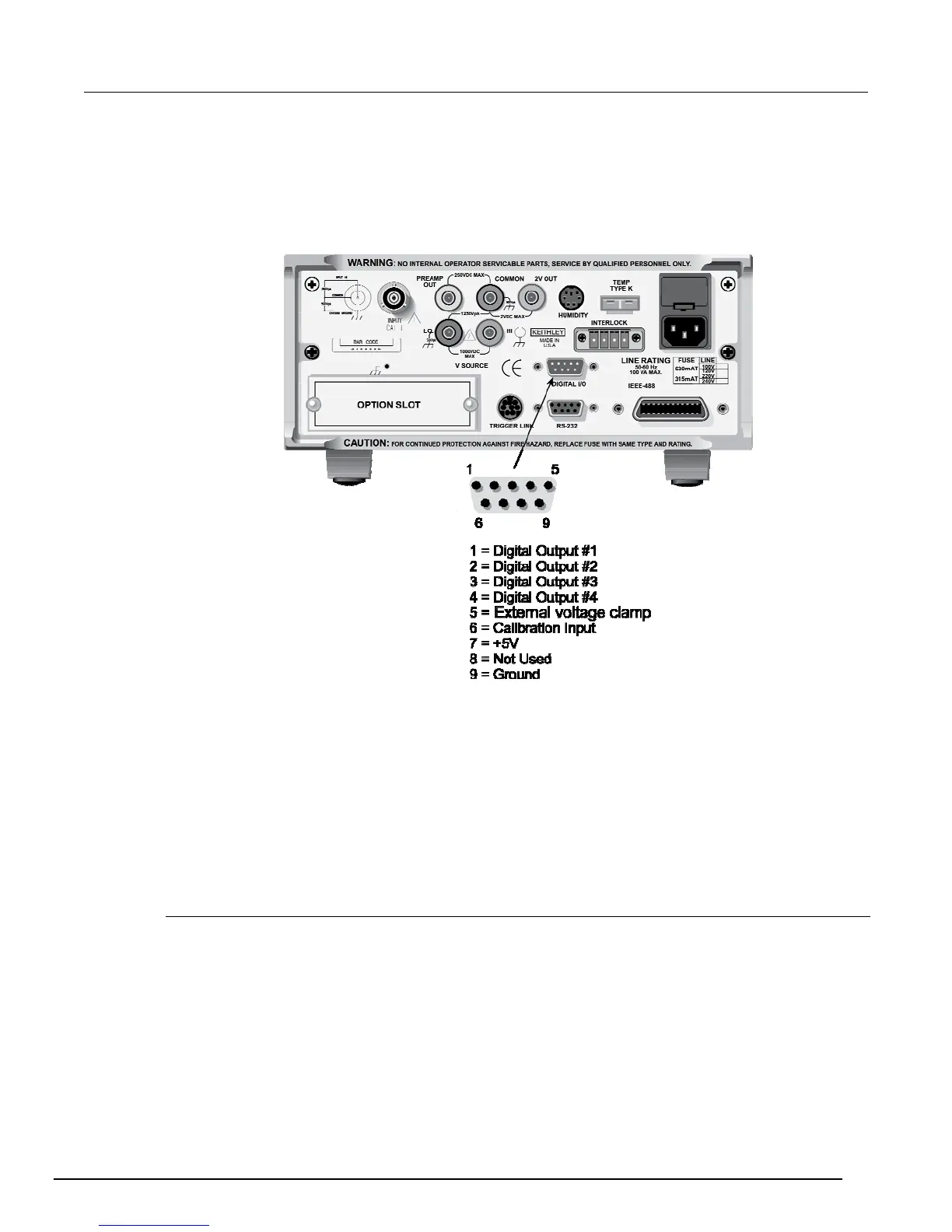
Digital I/O port
The Digital I/O port is a male DB-9 connector located on the rear panel. The port’s location and pin
designations are shown in the below graphic.
Figure 95: Digital I/O port
The Digital I/O port can be used to control external circuitry. The port provides four output lines and
one input line (input line is for calibration use only). Each open-collector output can be set high (+5 V)
or low (0 V) and sinks up to 100 mA. The four output lines can also operate external supplies from
+5V to +30V.
Use the DIGITAL I/O Menu to select the following options:
STATE: ON or OFF selectable for each output line (1 through 4); use to check or change the
output state
LOGIC-SENSE: ACTIVE-HIGH or ACTIVE-LOW selectable for each output line (TTL1 through
TTL4); use to check or change the output sense
Controlling digital circuitry
Each of the four digital open-collector outputs includes a built-in pull up resistor to +5 V. The output
transistor is capable of sinking up to 100 mA from voltages up to +30 V. The outputs can be
controlled independently or tied to one of four limit values (two high, two low).

 Loading...


