Model 6517B Electrometer Reference Manual Section 10: Limits, digital I/O, and scanning
6517B-901-01 Rev. C / August 2015 10-5
Limits example
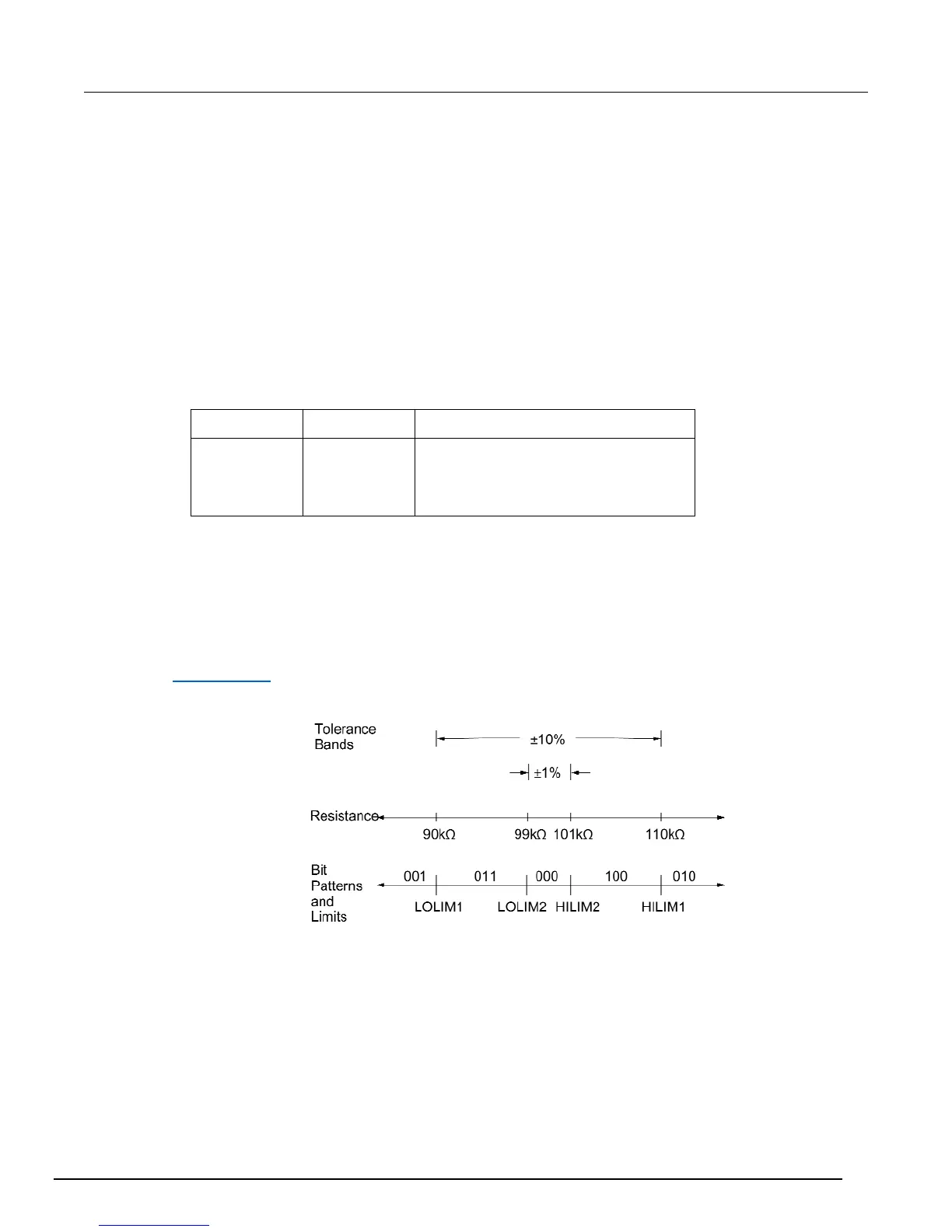
This example sorts a quantity of 100 k resistors into five "bins," according to the following
tolerances:
Values less than 90 k (outside -10 % tolerance)
Values greater than 110 k (outside +10 % tolerance)
Values between 90 k and 99 k (meets -10 % tolerance)
Values between 101 k and 110 k (meets +10 % tolerance)
Values between 99 k and 101 k (meets ±1 % tolerance)
The desired test is shown in the figure below. Use the following procedure to program the limits:
1. From the LIMITS menu, set the limit values and actions according to this table.
Limit Value Action
LOLIM1
HILIM1
LOLIM2
HILIM2
90 k
110 k
99 k
101 k
DIGOUT1=ON, others OFF
DIGOUT2=ON, others OFF
DIGOUT1=ON, DIGOUT2=ON, others OFF
DIGOUT3=ON, others OFF
2. Enable the binning strobe signal from the STROBE-CONTROL item of the LIMITS menu.
3. Set a pass pattern of all lines off from the PASS PATTERN item of the LIMITS menu.
4. Enable the control of the digital output lines by limit set #1 and limit set #2 from the LIMIT SET #1
and LIMIT SET #2 menus. This sets the digital output lines to the "pass pattern" (all OFF in this
example). Since binning is enabled, digital output #4 is also OFF.
Note that the actual state (high or low) of the digital output lines depends on the polarity (ACTIVE-
HIGH or ACTIVE-LOW). This is programmed from the DIGOUT selection of the GENERAL menu
(see Digital I/O (on page 10-6) below).
Figure 94: Using limit test to sort 100 kΩ resistors

 Loading...


