HANDLE MACHINE READY FOR INSTALLATION OF ATTACHMENT
3.
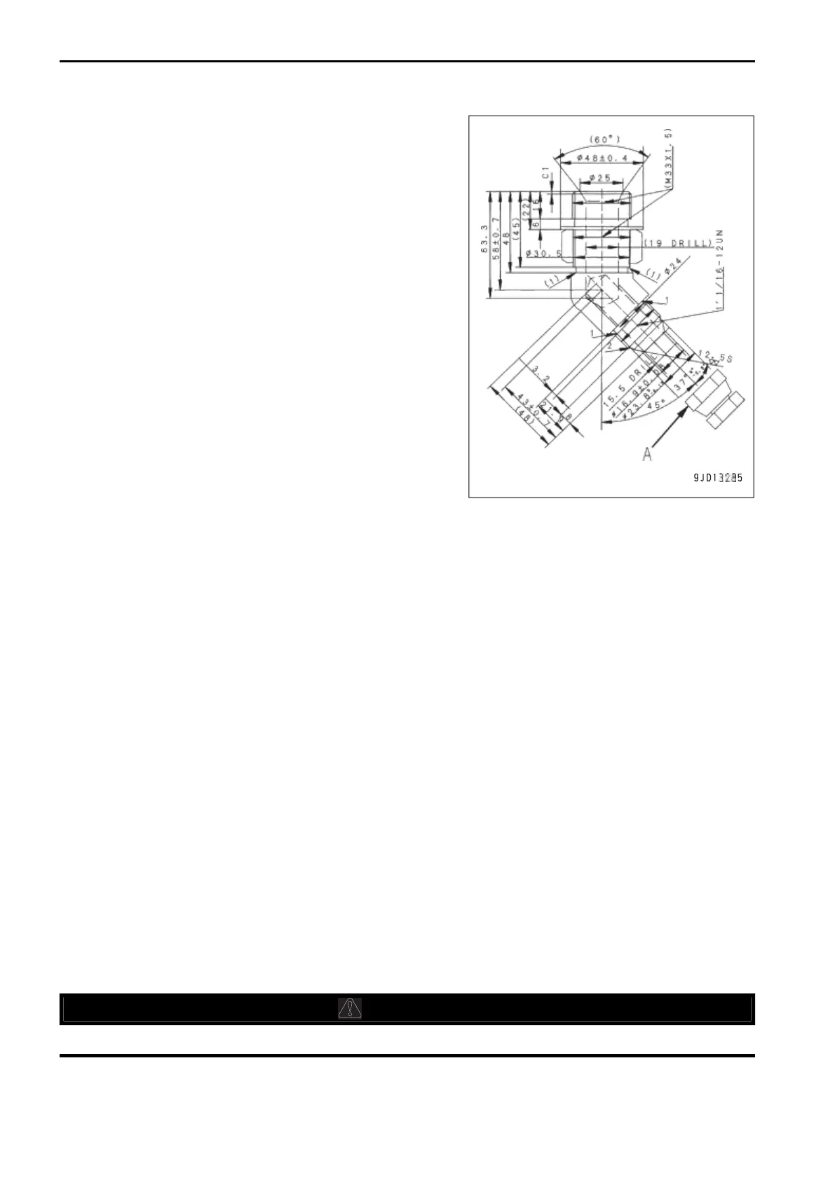
Connect the attachment piping provided by the attachment
manufacturer.
The dimensions on the machine body side are shown in
the figure. As for the dimensions on the attachment side,
consult the attachment manufacturer.
(A): Plug
4.
After connecting the piping, bleed air from the circuit ac-
cording to the following procedure.
NOTICE
If the air bleeding procedure is specified on the attach-
ment by the manufacturer, bleed the air according to
that procedure.
1)
Start the engine. For details, see “METHOD FOR
STARTING ENGINE (3-153)”.
Run the engine at low idle for 10 minutes, and then
start the following work.
2)
To bleed all air from the attachment circuit, operate the
attachment operation pedal repeatedly (approximately
10 times) while running the engine at low idle.
3)
After completing the air bleeding, stop the engine,
leave the machine for 5 minutes, and then start the operation.
The air bubbles in the oil inside the hydraulic tank are discharged.
4)
Check that there is no leakage of oil and wipe off any oil that is spilled.
METHOD FOR SWITCHING HYDRAULIC CIRCUIT
Depending on the type of attachment, set the working mode on the monitor as follows.
The hydraulic circuit and the set pressure of the safety valve in the service valve switch according to the selec-
ted working mode.
Depending on the attachment, it is necessary to change the oil flow in the service circuit.
For setting of the flow, see “METHOD FOR OPERATING ATTACHMENT (6-26)”.
Switching method of breaker and general attachment
Install an optional attachment and set the working mode to B mode.
Hydraulic oil flowing through breaker circuit passes through additional filter for breaker. Relief valve is set to low
pressure. Maximum oil flow can be adjusted in user mode.
Set pressure of safety valve of service valve (when shipped from plant): 17.2 MPa
Breaker circuit (one-way circuit) is formed.
Crusher or other attachment with 2-way circuit
Install an optional attachment and set the working mode to ATT/P or ATT/E mode.
Hydraulic oil flowing through crusher circuit does not pass through additional filter for breaker. Relief valve is set
to high pressure. Maximum oil flow can be adjusted in user mode.
Set pressure of safety valve of service valve (when shipped from plant): 24.5 MPa
Crusher circuit (2-way circuit) is formed.
METHOD FOR REMOVING AND INSTALLING ATTACHMENT
Lower the attachment to the ground and stop the engine.

 Loading...