THE 3-POINT HITCH SETUP
1. Make preparations for attaching implement.
• Selecting the holes of lower links on page 80
• Selecting the top link mounting holes on page
80
• Drawbar on page 81
2. Attaching and detaching implements
WARNING
T
o avoid personal injury or death:
• Be sure to stop the engine and remove the
key.
• Do not stand between the tractor and
implement unless the parking brake is
applied.
• Before attaching or detaching the
implement, locate the tractor and implement
on a firm level surface.
• Whenever an implement or other attachment
is connected to the tractor 3-point hitch,
check the full range of operation for
interference, binding or PTO separation.
• Lifting rod (right) on page 81
• Top link on page 81
• Telescopic stabilizers on page 81
• Telescopic lower links [CAB model] on page 82
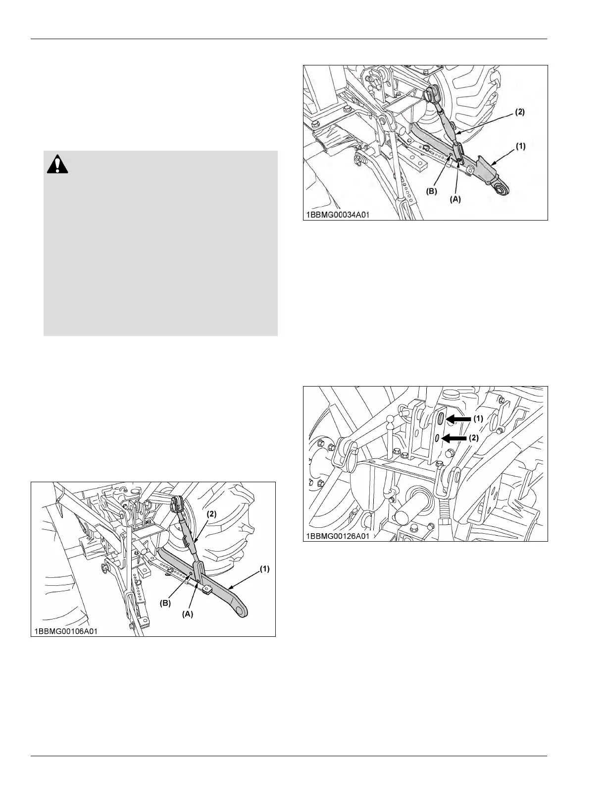
1. Selecting the holes of lower links
There are 2 holes in the lower links. For most
operations,
the lifting rods should be attached to the (A)
hole.
ROPS model
(1) Lower link
(2)
Lifting rod
(A) Hole
(B) Hole
CAB model
(1) Lower link
(2)
Lifting rod
(A) Hole
(B) Hole
NOTE :
• The
lifting rods may be attached to (B) hole for
greater lifting height.
2. Selecting the top link mounting
holes
Select the proper set of holes.
(See Hydraulic
control unit use-reference chart on page
89.)
(1) Top link mounting hole 1
(2)
Top link mounting hole 2
IMPORTANT :
• When
storing the top link in its bracket, the top
link pin may damage the rear glass of the CAB.
Remove the pin from the hole at the end of the
top link and insert it in the unused top link
mounting hole.
3-POINT HITCH AND DRAWBAR THE 3-POINT HITCH SETUP
 Loading...