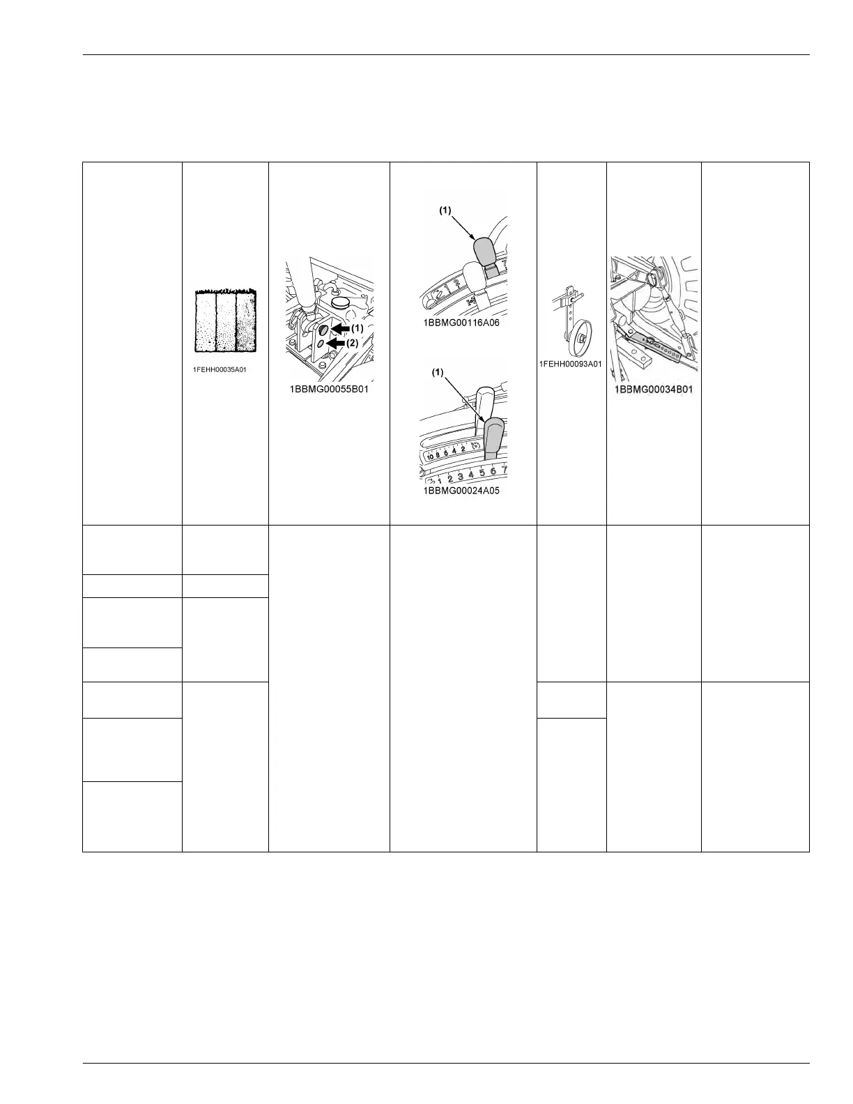
4. Hydraulic control unit use-reference chart
In order to handle the hydraulics properly, the operator must be familiar with the following.
Although
this information may not be applicable to all types of implements and soil conditions, it is useful for general
conditions.
Implement
Soil condi-
tion
Top link mounting
holes
ROPS model
CAB model
(1) Position control lever
Gauge
wheel
(1) Telescopic
stabilizers
Remarks
Moldboard plow
Light soil
Medium soil
Heavy soil
Hole 1:
Hole 2 is used only
when there is some
obstacle that pre-
vents you from using
the hole 1.
Position control
Yes/No Loose
Insert the set-pin
through the slot on
the outer tube that
align with one of
the holes on the
inner bar
.
For implements
with gauge
wheels, lower the
implements to the
ground.
Disc plow -
Harrow (spike,
spring-tooth,
disc type)
-
Subsoiler, etc.
Weeder, ridger,
etc.
-
Yes
Tighten
Telescopic stabiliz-
er should be tight
enough to prevent
excessive imple-
ment movement
when implement is
in raised position.
For implements
with gauge
wheels, lower the
implements to the
ground.
Earth mover,
digger, scraper,
manure fork,
rear carrier, etc.
Yes/No
Mower (mid-and
rear-mount type)
Hay rake, ted-
der, etc.
REMOTE HYDRAULIC CONTROL SYSTEM (IF EQUIPPED) HYDRAULIC UNIT
 Loading...