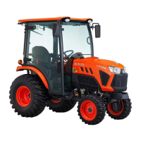
(1) Top link mounting hole 1
(2)
Top link mounting hole 2
3. Drawbar
Remove the drawbar if a close-mounted implement is
attached.
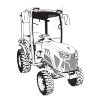
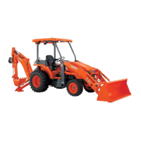
4. Lifting rod (right)
Level a 3-point mounted implement from side to side by
turning
the adjusting handle to shorten or lengthen the
adjustable lifting rod with the implement on the ground.
After adjustment, tighten the lock nut securely.
ROPS model
(1) Adjusting handle
(2)
Lock nut
CAB model
(1) Adjusting handle
(2)
Lock nut
5. Top link
1. Adjust
the angle of the implement to the desired
position by shortening or lengthening the top link.
2. The proper length of the top link varies according to
the type of implement being used.
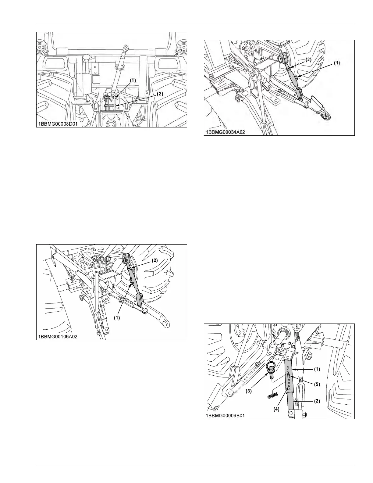
6. Telescopic stabilizers
1. Adjust
the telescopic stabilizers to control horizontal
sway of the implement.
Select the proper set of holes.
(See Hydraulic control unit use-reference chart on
page 89.)
2. After aligning satisfactorily, insert the set-pin
through any one of the holes on the outer tube that
align with one of the holes on the inner bar and both
stabilizers will be locked.
If the set-pin is inserted through the slot to engage
one of the holes on the inner bar, a limited degree
of sway will be permitted.
(1) Outer tube
(2) Inner bar
(3) Set-pin
(4) Hole
(5) Slot
THE 3-POINT HITCH SETUP 3-POINT HITCH AND DRAWBAR
 Loading...