2.3 Loader/remote control valve lever
1. Before
moving the lever, make sure that the
hydraulic hoses for attachments are connected.
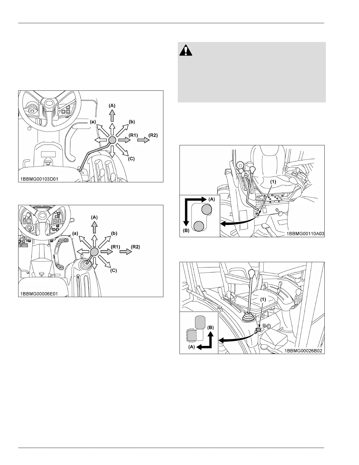
2. Move the lever diagonally ((a), (b), (c) shown in the
figure), and the first and second segments can be
controlled simultaneously.
ROPS model
(A) “FLOAT”
CAB model
(A) “FLOAT”
NOTE :
• Move
the lever to the “FLOAT” position, and
it will be held there by the detent
mechanism. To use the valve as a floating
valve with detents, connect the hydraulic
hoses to ports [A] and [B].
• When taking off hydraulic power from port
[D], the flow rate can be adjusted in 2 stages
with the lever.
The flow rate is high at position (R1) and low
at position (R2). Move the lever to position
(R1) or (R2) depending on the attachment in
use.
2.4 Valve lock
WARNING
T
o avoid personal injury or death from crushing:
• Do not utilize the valve lock for machine
maintenance or repair.
• The valve lock is to prevent accidental actuation
when implement is not in use or during
transport.
The control valve is equipped with a valve lock feature.
The control valve is locked in the “LOCK” position.
The lock is not intended and will not prevent a leak
down of the implement during the period of storage.
ROPS model
(1) Lock lever (A) “UNLOCK”
(B)
“LOCK”
CAB model
(1) Lock lever (A) “UNLOCK”
(B)
“LOCK”
REMOTE HYDRAULIC
CONTROL SYSTEM (IF
EQUIPPED)
The hydraulic auxiliary control valves can be installed
with up to 2 segments.
HYDRAULIC UNIT AUXILIARY HYDRAULICS
 Loading...